Description: This guide describes ways to consider the risk of chemical accidents in the placement of production facilities (plants) that handle or store hazardous chemicals and the planning of off-site land use and zoning.
Target group: The guide is intended for the planning and establishment phase of new production plants, the assessment of significant changes therein, and in the planning of land use around the plants.
Date: 24 June 2025
Limit value for acute exposure that describes the health effects of a chemical, see annex 1.
BLEVE (Boiling Liquid Expanding Vapor Explosion)
Rapid vaporisation of a pressurised liquid, when the liquid suddenly expands due to a fracture in the pressure vessel. Most commonly, BLEVE occurs when a metal container heats up beyond its design temperature. If the liquid is flammable, it is possible to use the term hot BLEVE, and if the liquid is not flammable, a possible term is cold BLEVE.
A hot BLEVE requires an external heat load (fire, jet fire), which causes the flammable liquid inside the vessel to heat up sufficiently above its atmospheric boiling point. A cold BLEVE does not require an external heat load; it can also be caused by mechanical damage, overfilling or other pressure increase unrelated to heating.
BLEVE is not possible with vessels that cannot withstand hyperbaric pressures, which allow that the liquid can heat up above its boiling point. Safety valves, fire protection and siting of the container away from fire hazards reduce the risk of BLEVE.
A BLEVE fractures the vessel, fully releasing and expanding its contents at once. Due to rapid vaporisation, the volume of the released substance may expand 100-fold in an instant. If the vaporising substance is flammable, such as LPG, it ignites a significantly high-power explosion that burns out in a short period of time. This forms a rising ball of fire. With a large container (in the 100 m3 range), the fireball may grow to hundreds of metres in diameter and radiate significant heat for several hundreds of metres.
There are detailed definitions of a BLEVE in the literature. For example, see BLEVE fireball
Boil-over
A boil-over refers to an abrupt and strong burst of flammable liquid from a vessel. It is the result of a layer of water (e.g. due to the extinguishing of a tank fire) under a hot combustible viscous hydrocarbon (e.g. oil) floating on top of water. As the fire progresses, the temperature of the oil heats the water above its boiling point, which suddenly evaporates the water to penetrate through the oil as bubbles. Due to the viscosity of oil, this creates significant turbulence, which, upon reaching the combustible surface, ignites and may cause an explosive spread of the fire. Splashes may reach to a few hundred metres away, depending on the size of the tank.
ERPG (Emergency Response Planning Guidelines)
Limit value that describes the health effects of a chemical, see annex 1.
Sensitive target
Sensitive target are defined in section 8.2 of the Chemical Safety Decree 856/2012: “Particular attention must be paid to sensitive targets of human and population health, such as care facilities, health centres, shopping centres, schools, daycare centres, meeting rooms and areas, residential areas, transport hubs and other locations sites that may simultaneously feature large numbers of people, which may be particularly difficult to leave or take cover in the event of an accident.”
Flash fire
A short-duration gas or steam fire that does not generate pressure in which the flue gases can expand freely.
IDHL (Immediately dangerous to life or health)
Limit value that describes the health effects of a chemical, see annex 1.
Pressure Vessel Burst/Rupture
Burst of a pressure vessel that causes a powerful, outward pressure wave. The pressure wave also carries pieces of the pressure vessel and objects caught in the wave.
Vapour Cloud Explosion, VCE
A vapour cloud explosion occurs when a large amount of flammable gas releases or evaporates to form a flammable mixture with air, which then ignites. Depending on the velocity of the flame front, vapour cloud explosions can be deflagrations (typical) or, possibly, detonations. Deflagration to detonation transitions are also possible.
The delayed ignition of a high-pressure hydrogen gas leak will result in a vapour cloud explosion in which the turbulence of the gas jet will further accelerate the flame, causing considerable overpressure. This phenomenon is called a ‘jet explosion’. This phenomenon is only known to occur with hydrogen or is very rare with other chemicals.
A zone around production facilities where it is necessary to investigate and consider the risk of accidents when making assessments and decisions on land use. It is mandatory to request a statement from Tukes and the rescue authorities unless the risk of an accident or its impact on land use is already known. Tukes defines consultation zones based on the resulting accident impact analyses and known accident risks typical of the industrial process in question. The size of the consultation zone varies between 0.2–2 km, depending on the hazard posed by the plant. As a rule, the consultation zone is calculated from the property line. The consultation zone is not the same as the safety distance (see definition of safety distance).
Pool fire
Leakage and combustion of flammable liquid on the ground or other surface. The maximum area of the fire is limited to the size of the basin, container or other equipment or topography that restricts the spread of the liquid. Tank and barrier fires are pool fires.
Thermal radiation
In an accident, thermal radiation is usually the result of a fire. Strong thermal radiation can propagate a fire and cause burns. The intensity of thermal radiation at a certain distance means the radiant power of the flame for a given surface area (kW/m2).
Thermal Dose Unit, TDU
The thermal dose unit is a function of the intensity of thermal radiation and the exposure time. At short exposures, the severity of burns depends on the thermal dose unit, as high intensity is more harmful in the same time unit than low intensity. The general formula for the thermal dose unit is TDU = (kW/m2)4/3 s
Pressure
Pressure is the force exerted on a wall by an expanding gas, the weight of a fluid or flow thereof, divided by the area of the wall. Pressure can be expressed as absolute pressure, overpressure or underpressure. In the SI system, the unit of pressure is the pascal (Pa), which is the force of one Newton per square metre (N/m2). The technology sector often uses the bar as the unit for pressure. The conversion ratio is: 1 bar = 100 kPa. For example, normal atmospheric pressure is 1.01325 bar = 101.325 kPa.
Absolute pressure (bara, bar absolute) Pressure in relation to an absolute vacuum. Absolute pressure is used to examine the thermodynamic and flow characteristics of a substance.
Gauge pressure (barg, bar gauge): Pressure in relation to atmospheric pressure. Commonly used method to measure pressures (more useful).
Pressure wave: The momentary change in the state of a gas at its explosion point into the environment, in which the density, pressure and flow rate of the gas change. The front of the pressure wave can be either continuous or discontinuous. A continuous front of the wave is called a soft or gradual pressure wave, and a discontinuous front is called a shock wave. A pressure wave that is propagated from a deflagration may transform into a shock wave. The pressure wave is indicated as an overpressure, typically in kilopascals (kPa) or bars.
Pressure wave reflection: A pressure wave that reflects off a wall or similar obstacle. The size and direction of a reflected wave depend on the angle of incident between the pressure wave and the wall. When perpendicular to a wall, the flow of gas stops entirely and causes the largest rise in pressure. The overpressure of a reflected, perpendicular wave is always at least twice that of the original shock wave.
Over/underpressure: The difference between actual pressure and ambient air pressure. The magnitude of stress on structures and other objects is directly proportional to the over/underpressure. These are typically used to examine pressure resistance.
Overpressure impulse: In addition to overpressure, a pressure wave also features an overpressure impulse. It depends on the amount of overpressure and its duration. A more specific definition of overpressure impulse is the integral of overpressure versus time and is indicated as Pascal-seconds (Pas). The combination of a pressure wave’s impulse and the overpressure damages structures and people with its momentum. When assessing structural damage, it is necessary to consider the overpressure and its impulse, as well as those of the underpressure.
Roll-over
Roll-over refers to a situation in which layers of liquid in a tank at different temperatures or densities mix (roll over) suddenly, causing a rapid and dangerous increase in pressure in the tank. Liquefied natural gas (LNG) is the most common chemical associated with the risk of a roll-over.
Jet fire
Combustion of a pressurised flammable gas or liquid that is released in a particular direction as a jet-like long flame.
Safety distance
Safety distance refers to the permissible distance of a hazardous object to protected sites, such as a neighbour’s property line or a residential building. Safety distance is measured from outer edge of a hazardous object, such as a chemical tank, barrier or process unit, to the protected site. It can be considered to be one protective layer or a method of risk management against an accident. Concurrently, it is important to understand that a safety distance can never be the only way to prevent accidents and limit the consequences; plants are required to put various preparatory measures in place. Safety distances shorter than what is presented in this guide can be applied in situations where a similar protective effect can be demonstrated through risk assessment and further technical safety solutions or by changing the plant implementation. Neither does meeting a safety distance mean that further measures to prevent accidents or development of process safety at the plant are no longer required.
Major accident
Major accidents are defined in section 6(17) of the Chemical Safety Act 390/2005: “A notable discharge, fire, explosion or other event that is a consequence of uncontrollable events in the operation of a production plant that can cause serious or immediate danger to human health, the environment or property, or danger that becomes evident later inside or outside the plant and that is related to one or several hazardous chemicals or explosives.”
Major accident-prone production plant
A production facility subject to the Seveso Directive that requires a safety report or major-accident prevention policy pursuant to the Chemical Safety Act (390/2005). These obligations are determined by the quantities of chemicals at the plant and their level of hazard.
Production plant
For the purposes of this guide, the term production plant (or plant) refers to both plants that manufacture or use hazardous chemicals and their stocks (container or bulk storage).
Minimum (safety) distance
Minimum distance refers to the minimum safe distance of a hazardous object from protected sites. The minimum distance differs from the safetysafety distance in that it cannot be changed with technical solutions or other risk control measures.
1 Introduction
This guide describes ways to consider the risk of chemical accidents in the placement of production facilities (plants) that handle or store hazardous chemicals and the planning of off-site land use and zoning. The guide also discusses the siting of production plants from the perspective of pressure equipment legislation.
The guide is intended for the planning and establishment phase of new production plants, the assessment of significant changes therein, and in the planning of land use around the plants.
The guide can also be used in the layout design of a production plant to assess sufficient distances between different functions and equipment. However, the guide does not specify safety distances within the plant; these must be resolved at the planning stage through hazard and result analyses. On-site safety distances are available in, for example, standards. Layout design or assessment of on-site safety distances may also lead to requirements on the size of the plant buildings or area.
There are various laws that govern the siting of production plants. The most important regulations regarding chemical accident hazards are:
Act on the Safety of Handling of Dangerous Chemicals and Explosives (“Chemical Safety Act”) (390/2005);
Government Decree on the Safety Requirements for the Industrial Handling and Storage of Dangerous Chemicals (“Chemical Safety Decree”) (856/2012);
Land Use and Building Act (132/1999), ongoing amendment process
Construction Act (751/2023)
Pressure Equipment Act (1144/2016)
This chapter compiles the most important requirements on how the hazard risk of a plant must be considered in the planning of its placement.
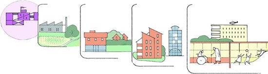
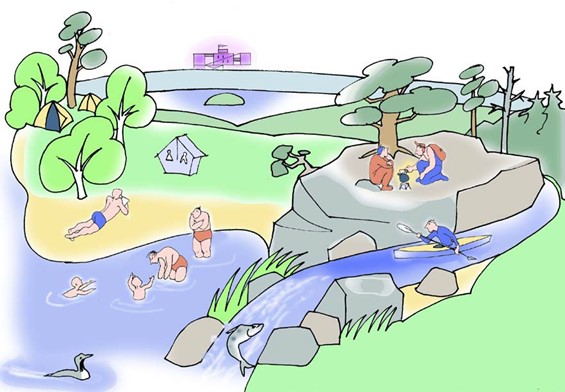
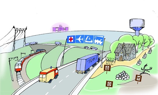
The distance of an accident-susceptible plant must be sufficient from sensitive sites, especially ones where people may be present. The more sensitive the target (school, hospital, daycare centre etc) or type of land use, the further they must be from hazardous plants (figure 1). In this context, a sensitive target means a site, where there may be a large number of people who are exposed to the impacts of an accident and that the people at the site have reduced ability to act in the event of an accident.
The plant must also be a sufficient distance away from other industries, nature preserves and other important environmental protection sites.
Figure 1: The principle for placing production plants is that sensitive targets must remain as far away as possible from hazardous sites
2.1 Chemical safety legislation
In European Union regulation, chemical hazards are controlled through directive 2012/18/EU on the control of major-accident hazards involving dangerous substances, amending and subsequently repealing Council Directive 96/82/EC on 4 July 2012 (Seveso III directive) (2012/18/EU). The directive applies to more than 12,000 production plants in the EU.
The directive gets its name from Seveso, a small Italian town where a chemical plant accident caused a spill of poisonous dioxin to a large area. Seveso III obliges operators to take all necessary measures to prevent major accidents and to limit their consequences (Article 5). According to the directive, Member States must, in their land use planning, make sure that production plants are a sufficient distance away from other functions of society and valuable natural sites (Article 13).
In Finland, the obligations of the Seveso III directive have mainly been implemented through the Chemical Safety Act (Act on the Safety of the Handling of Dangerous Chemicals and Explosives 390/2005) and supplementary decrees. The competent authorities are the Finnish Safety and Chemicals Agency (Tukes) and local rescue authorities. Land use, land use planning and construction are governed by other legislation. Requirements concerning the siting of plants are laid down in the Government Decree on Safety Requirements for the Industrial Handling and Storage of Dangerous Chemicals 856/2012. These regulations apply to approximately 1,000 production plants in Finland, which are supervised by Tukes.
Sections 17–20 of the Chemical Safety Act (390/2005) are essential for the siting of a production plant. Based on these sections, the siting process must take the following into account:
Land use in the plant area (section 17);
Nature sites and groundwater areas (section 18);
Activities outside the plant and natural conditions do not pose a risk to the plant (section 19);
The plan for the plant site, the intended use indicated in the plan, and planning regulations (section 20).
Chapter 2 (sections 4–20) of Decree 856/2012 contains more detailed principles and requirements on the siting of a plant:
siting principles (sections 4–5);
taking the thermal radiation, pressure and health hazard caused by an accident into account in the siting (sections 6–8);
nature sites, key functions of society or sites with cultural and historical importance (sections 9 and 11);
groundwater protection (section 10);
siting requirements for various chemical stores and process equipment (sections 12–20).
Chapter 3 of Decree 856/2012 deals with the siting of equipment and buildings within a production plant.
In siting a production plant, the intended uses and plan regulations indicated in plans with a legal effect must be taken into account for the plant site and its surroundings. Plans with a legal effect include master plans and detailed plans that are in effect and some regional plans. The suitability of the planning is determined both when applying for a chemical safety permit for a new production plant and in connection with material changes to the operation (change permit). The plant site refers to the plot or property in which the production plant is sited. The surrounding area of the plant site refers to the area in which it is required to assess the impacts of a potential accident (consultation zone). The siting requirements for a plant are assessed on the basis of its accident impact analyses.
A plant may not be sited in a groundwater area without a specific, justified reason. Siting in groundwater areas is not completely prohibited, but when choosing the plant site, a careful assessment is required of the impact of a chemical leak to groundwater and the measures to protect the groundwater in the case of a leak. These matters are also addressed in the Environmental Protection Act (527/2014).
There is a separate decree for liquefied petroleum gas plants, which lays down the basic requirements for construction and siting Government decree on the safety requirements for liquefied petroleum gas plants (858/2012). There are detailed instructions on siting LPG plants in this guide.
Provisions on the treatment of natural gas and biogas are laid down in the Government Decree on the Safety of Natural Gas (551/2009). The Natural Gas Decree lays down all basic requirements for construction, installation, inspection, use and supervision as well as measures in the event of damage and accidents. There are also instructions and guides for the processing of natural gas and biogas on the Tukes website Natural gas and biogas.
In addition to the requirements described in this guide, there may also be other regulations, requirements and conditions that must be considered in the siting of a production facility. Examples include the Construction Act, construction in the vicinity of power lines or transport routes, gas transmission and distribution pipework, etc.
2.2 Pressure equipment legislation
Pressure equipment legislation comprises the Pressure Equipment Act (1144/2016), the Pressure Equipment Directive (2014/68/EU), the Government Decree on Pressure Equipment (1548/2016) and the Government Decree on Pressure Equipment Safety (1549/2016).
Pressure equipment and their assemblies must meet the safety requirements laid down in legislation when they are brought to market or put into service at a planned site. A piece of pressure equipment may not be a hazard to health, safety or property.
If registered pressure equipment or boilers subject to pressure equipment legislation are sited in the area, general legal requirements must be followed. These include the siting plan, the registration of pressure equipment in the plant, and the appointment of a supervisor and deputy supervisor of the use of pressure equipment.
Section 7 of the Government Decree on Pressure Equipment Safety (1549/2016) lists pressure equipment that an inspection body must inspect the siting plan of. A piece of pressure equipment must not be installed until the siting plan has been inspected.
An inspection of the investment plan is required for at least the following pressure equipment:
a boiler that requires registration
an autoclave with a product of the maximum allowable operating pressure and volume of more than 1000 bar × litres
a pressure vessel that is placed indoors, in a public space or in the immediate vicinity of a public access, with the product of the maximum allowable operating pressure and volume readings exceeding 10,000 bar × litres
mobile pressure equipment or a combination of gas cylinders placed indoors, in public spaces or in the immediate vicinity of a public access, with a capacity exceeding 450 litres. See instructions Pressure equipment for automatic fire extinguishing equipment (pdf. in Finnish)
Description of a boiler plant surrounding area
Boiler plants require a hazard assessment that also describes their surrounding area. This description of the plant environment serves as an overview of the risks surrounding the installation in support of the risk assessment, to identify possible domino effects and guide land use planning in the surrounding area of the plant. The main forms of land use and functions around the plant within a 200-metre radius must be described for the site. More information on the subject is available in the Hazard analysis guide for boiler plants (in Finnish).
3 Assessment of the plant site along with the land use and planning of its surrounding area
The risk of accidents caused by the production facility and land use planning are vital when siting a production plant. Firstly, the operator must be aware of the risk of accidents caused by its plant and the effects thereof. Secondly, it is necessary to consider the detailed plan of the production plant site (the plot) and its surrounding area, and the restrictions the detailed plan imposes on the operation of the production plant.
The siting of a production plant is a comprehensive matter in which it is necessary to take the accident impacts of the plant, the plot of the site and the use of its environment into account.
3.1 What must be done to investigate the risk of accidents for a plant?
The risk of accidents for a production plant is determined by identifying accident scenarios that are relevant for the siting and by carrying out impact analyses of the impact areas of these scenarios.
This guide (chapter 4 in particular) provides guidance and criteria for selecting accident scenarios and preparing impact analyses. Chapter 5 of this guide contains ready-made tables of safety distances for smaller plants, for which the conditions and process hazards are well known, making it possible to determine safety distances for them based on reliable accident modelling. If conditions apply to the use of these safety distances, they are explained separately.
In general, accidents that involve hazardous and volatile or gaseous chemicals have a larger impact area than accidents caused by explosions or fires.
3.2 Siting assessment of a new plant
It is necessary to survey the accident risks and impact areas of a new production plant or a significant expansion of an existing plant at the beginning of the investment project. Usually this is much earlier than the plant permit application is submitted to Tukes. It is important to identify the hazards associated with the chosen technology and chemicals in the early stages of the investment project. In the selection of primary equipment sizes and chemicals, an effort must be made to follow the principle of intrinsic safety and the obligations of the operator under section 8 of the Chemical Safety Act (390/2005). It is an obligation to introduce the least hazardous chemical or method.
It is not allowed to site a new plant where an accident could cause intolerable or unacceptable environmental and human impacts in accordance with the legislation or this guide or if the accident could prevent or hinder the implementation of legal plans for the surrounding area of the site. The Tukes permit process typically takes place during the detailed planning or construction phase of the plant, when many matters related to the siting have already been decided. It is useful for an investment projects and its permits that the operator draws up a separate plan for the investment project that covers the necessary risk analyses and models from the perspective of process safety and siting, in addition to where these analyses take place in the implementation of the investment.
Ultimately, Tukes makes the decision on the location of the plant in the chemical safety permit, but as it is usually not possible to start the permit process before the location is selected, it is highly recommended that the operator contacts the municipal planning authority and Tukes immediately in the early stages of the project. The chemical safety permit application must be accompanied by a report on the detailed plan of the production plant site and the surrounding areas. If necessary, Tukes will request a statement from the municipal planning authority on the suitability of the site plan and/or plan of the surrounding area during the chemical safety permit processing.
3.2.1 Environmental Impact Assessment (EIA)
If the project is subjected to an environmental impact assessment process, it must include an impact assessment of accidents at the planned production facility and the suitability of the detailed plan. This requires that the chemicals of the planned project and the sizes and conditions of its processing equipment can be initially approximated to carry out accident modelling. The EIA process should provide the operator and the authorities an assessment of the suitability of the site plan and the possible restrictions caused by plans in the surrounding area in relation to the risk of accidents caused by the production plant.
3.3 Detailed plan of the plant site
As a rule, the municipality makes decisions on land use and planning in its area. The intended use and planning regulations indicated in the legal plan of the chosen site should allow the planned operations. The operation must comply with the plan and its provisions. It is obvious that a production plant cannot be sited in a recreational or residential area.
The classification laid out in the Chemical Safety Act (390/2005) (authorised facility, facility that requires a major-accident prevention policy, facility that requires a safety report) guides the management of chemical safety, permissions and official controls.
When preparing detailed plans of areas for new major accident-susceptible plants in accordance with the SEVESO III Directive, it is recommended to use plan label T/Kem or, in the planning regulations, to indicate the suitability of the plan for a significant plant that stores or handles hazardous chemicals. Plan label T/Kem is also recommended for existing Seveso III-compliant plants if the plan for the area is amended. Plan label T/Kem refers to an industrial and storage area where it is allowed to site a major plant that manufactures or stores hazardous chemicals. A T/Kem plan or label in the planning regulations is a clear indication that the area plan is suitable for industry with a risk of major accident. The T/Kem plan label must be based on sufficient surveys conducted by the planner.
On a case-by-case basis, a plant for large-scale handling and storage of hazardous chemicals may also be sited in areas with other types of plan label, such as:
T (industrial and storage area),
TT (industrial area with significant environmental impact),
EN (energy supply),
ET (municipal engineering service area)
LS (port area)
In this case, the assessment covers whether the plant’s impact and nature match the general intended use indicated in the plan. It is important to assess the use and up-to-dateness of the plan when the plant’s accident impacts may extend significantly outside the plant area, or the risks of the operation are clearly different from what currently exist in the area or is defined in the plan. When building a new plant or expanding an existing one, it is essential to review the studies on which the plan is based to make sure that they are sufficient from the perspective of the safety and environmental risks associated with the industrial handling or storage of hazardous chemicals. If necessary, the plan must be amended or supplemented to indicate that hazardous chemicals may be handled and stored at the site.
In addition to the plant plot, it is also necessary to take the plan labels of the surrounding plots into account. A new plant may not restrict the use indicated for the surrounding plots in the plan. In addition to the plan, the risks of accident arising from the plant are always assessed; suitability of the plan alone is not enough to ensure that the plant can be sited on a particular plot.
The clean transition siting permit is an indication that the plot of the production plant is suitable for the operation without a detailed plan or master plan. This permit is granted by the municipality where the plant is sited. According to section 46a(1)(11) of the Construction Act, a permit for the siting of production plants that manufacture, handle or store hazardous chemicals or explosives require that current and future legal plans for the environment of the site are considered. This requires an accident impact assessment for the plant. A clean transition siting permit pursuant to the Construction Act is not a guarantee that Tukes will issue a permit. Tukes permits are subject not only to the site plan but also to the accident impacts and accident prevention measures of the plant and the surrounding areas. In addition, the siting should also consider that the Land Use Act and its obligations also apply to the siting of plants with a major accident risk.
3.4 Consideration of the existing land use at the site and surrounding areas of a new plant
According to the Chemical Safety Act, a new plant cannot be sited in a way that its accident impacts prevent or hinder the implementation of legal plans in the surrounding areas of the site. The assessment should consider also the area to which the accident impacts, assessed in accordance with this guide, may extend. The operator must find out the intended uses and regulations of the legal plans in the impact area of the accidents as well as the existing functions and settlements in the area.
Examples:
A day-care centre has been designated in the legal plan on the neighbouring plot of the planned production plant site, and models show that the impact of a major accident would reach the planned day-care plot. In this case, the accident impacts would prevent the implementation of the day-care centre plan, which means the plant cannot be sited in the planned location.
The area may have been converted from a residential area to an industrial area. In this case, persons who still reside in the area may prevent the siting of the plant if the impact of a major accident extends to residential properties.
Particular attention must be paid to these forms of land use: residential areas, schools, care facilities, large commercial units, transport routes, and other forms that may simultaneously and regularly include many people.
3.5 Planning and construction in the vicinity of existing production plants
It is necessary to take the risk of accidents for production plant into account in the planning of land use in the surrounding areas to achieve an adequate distance between a hazardous site and sensitive sites. A production plant that handles and stores large amounts of hazardous chemicals may restrict land use and construction in its surroundings due to its accident impacts.
To consider the accident impacts, Tukes has defined a consulting zone for each production plant under its supervision. In such a zone, changes to the plan and significant construction (such as a sensitive target) require a statement from Tukes and the rescue authority. The consultation zone is not a safety zone or distance, but an area where it is necessary to study the impact of the accident hazard on land use. As a rule, the consultation zone extends for 0.2–2 km from the property line. Tukes submits the list of plant consultation zones to the records offices of the municipalities, regional councils, rescue authorities and the Finnish Supervisory Agency every year. Tukes recommends that consultation zones or more detailed safety distances should not be drawn on published plan maps, as they may change or be confidential.
In a consultation zone, accident impacts are viewed through the criteria of this guide in the same way as the siting of a new production plant. In its statements, Tukes draws on the plant’s impact analyses or other severity and scope assessments of accidents. Tukes assesses additional construction in relation to the existing risk of accidents, taking the functions already in the affected area, the number of people and the general conditions for sheltering inside buildings or safe evacuation into account. Furthermore, additional construction around the plant must not pose a risk to the operation of the plant (e.g. increased risk of fire).
4 Accident impact modelling and impact assessment criteria
4.1 Impact analysis and safety distances
A chemical accident typically starts with a leak. There may be several reasons for the leak, but depending on the hazardous properties of the chemicals, it may lead to an explosion, fire, the spread of a toxic substance or a combination of these. This chapter describes ways to assess the impact of chemical accidents and determine the plant’s safety distances. The basis to determine safety distances is in the accident impact areas and impact thresholds, which are the result of the impact analyses. In many EU countries, safety distances are based on permissible risk levels (probability of individual or collective death), which are determined in regulations or by the authorities, which are not defined or used in Finland. The probability of accidents and related impacts (damage) on people is considered by providing guidance in the selection of scenarios and modelling parameters, and by setting lower thresholds (minimum tolerable adverse effect) for sensitive targets.
This chapter presents the accident types or scenarios that must be selected for modelling from the perspective of the plant’s siting and land use planning. The models are based on major accidents, while eliminating rare incidents such as full pipe rupture or an underground LPG tank BLEVE fire. With uniform modelling criteria, the conditions that restrict operations and land use are kept equal for everyone.
Always model accidents without the anticipated control measures and protective layers. This means that the modelling should not take, for example, automatic stop functions, scrubber systems for toxic gases or water spreading systems that limit thermal radiation into account, which would limit the impact of the accident. It is only allowed to include these protective functions or layers if the impact analysis is supplemented with a detailed risk assessment that demonstrates what happens after a leak occurs and how each specified protection layer affects the events. If the capability of the specified protection layers is found to be sufficient, and the original accident scenario model without protection layers becomes very unlikely, it does not need to be considered in the siting of the plant. Where necessary, this risk assessment must be complemented with a new impact analysis that considers the protective layers.
Different protective layers may not be equal. In other words, they may have different risk mitigation capabilities. The safety distance is also seen as one protective layer. Passive systems, such as safety basins or protective walls, are generally more effective and reliable than active systems that need energy or people to operate. Human activity always carries many uncertainties, which is why they cannot be used as a protective layer in a major accident. Safety basins and other similar leak management structures may be considered in impact analyses. Reliability or mitigation capability are also affected by how the accidents develop over time: for example, explosions are often very quick, which makes it more difficult to mitigate their impact compared to the effects of a fire or the spread of chemical leaks.
The model of the accident scenario should allow for the calculation of the intensity of thermal radiation (kW/m2), peak overpressure (bar, kPa) and chemical concentrations (ppm) at a certain distance at a certain time. When selecting for a scenario, it is necessary to fully take the various functions of the plant and their location in the plant area into account (e.g. an unloading and loading site on the edge of the plot).
4.1.1 Identification of accident scenarios
Possible accidents are investigated based on the hazardous properties and handling conditions of the chemicals in the plant.
Fires caused by fluid or gas combustion
Pool fire
Jet fire
BLEVE fireball
Flash fires (determining the fire hazard area)
Vapour cloud explosion
Leak of a toxic gas or fluid that vaporises in ambient pressure/temperature
Explosives are subject to separate safety distance requirements and are not covered in this guide. Models of explosions of pressure equipment and dust explosions are not required without a specific reason. There isn’t a requirement to model boil-over and roll-over phenomena, but risk management plans must take their prevention into account.
Modelling of solid or non-evaporating liquid chemical leaks into the environment (transport of leakage in the environment) is not required. However, it may be necessary to use reports on the severity of an environmental accident caused by chemical leakage or fire-fighting waste water to assess the effectiveness and reliability of recovery systems as part of the plant’s other process risk analyses. Properly designed and maintained safety basins and other similar leak control structures reliably retain chemical leaks and prevent further leakage into the environment.
4.1.2 Accident scenarios
Below is a list of accident scenarios that determine the siting of the hazardous chemical production plant along with the marginal conditions for the preparation of the models.
Pool fire
For flammable liquids, the model is of a fire of the largest storage tank and the safety basin around the tank. A fire in the safety basin may cover the flame of the tank fire horizontally and vertically, which means that it is often enough to model the fire in the safety basin. If the tank area is large and there are targets exposed to fire in different directions, it may be necessary to model more than one tank/safety basin fire or a fire in another restricted fire area (e.g. a ground slab). To determine the thermal radiation of a fire, a flammable liquid and the area of the fire must be known.
A pool fire caused by a leak in the piping system of the flammable liquid is modelled if the location of the piping system may cause an accident impacts outside the plant site. What is modelled is the worst possible leakage.
For outdoor bulk storage of liquid chemicals (IBC packages, barrels and containers) the largest catchment area or the surface area of the pool is modelled, taking into account the full amount of chemical in the pool area.
Jet fire
If a pressurised pipe or other equipment contains flammable liquid or gas, it is necessary to model the jet fire scenario for such a leak.
BLEVE fireball
If there are above-ground pressurised tanks of flammable and liquefied gas at the plant, the thermal radiation and pressure effects of the BLEVE fireball should be modelled. For LPG plants (see section 5.3), the BLEVE impacts are considered in the consultation zone. The model must include the maximum capacity of the tank (worst case scenario).
Deflagration and fire hazard area
For leaks of a flammable gas or fluid that evaporates in ambient pressure/temperature, it is necessary to model the deflagration caused by the leak. The fire hazard area is modelled with 50% and 100% concentrations of the gas cloud at the lower flammable limit (50% and 100% LEL). Anyone caught in the combusting cloud is likely to die of the sustained burns.
Storage building fire
It is not necessary to model the chemical fires in a building or its fire compartments. These fires are handled in the same way as a normal building fire.
If chemicals that form a toxic gas upon combustion are stored inside, it is necessary to model the spread of the toxic gas cloud. The need to model the toxic flue gases can be roughly assessed from the amount of chemicals in the fire with e.g. chlorine, fluorine or sulphur atoms, in which case normal flue gases (CO, CO2 and H2O) may contain substances that are more toxic. Possible causes of toxic compounds include combustion, pyrolysis, degradation or a reaction between degradation products. Flue gases from building material or other combustible material may be hazardous to health but are not required to be modelled.
If the production plant (stock) has aerosol containers that contain more than 150 tonnes of flammable material, the operator must assess the impact of an indoor explosion or justify why such an explosion is not possible in the conditions of the plant. In addition to the storage volume, at least the size of the warehouse (area), packaging methods, height of storage, layout and automatic fire extinguishing equipment have an impact on the explosion and its prevention. See e.g. RR916 - Risk assessment for VCE scenario in an aerosol warehouse (hse.gov.uk) and RC19: Recommendations for the storage of aerosol products.
Vapour cloud explosion
A vapour cloud explosion must be modelled for leakages of flammable gases and flammable liquids that vaporise at ambient pressure/temperature. The modelling must consider factors that affect the impact of the explosion, such as the point of leakage, the time and source of ignition, the properties and phase of the chemical, the mass of the combustible substance in the flammable vapour cloud, and the congestion and confinement of the space in the area of the flammable vapour cloud. Structures in the area that limit obstacles or space include buildings, shrubs and other vegetation, equipment, and pipelines.
The ignition of the gas cloud must be set at the time when the explosion causes the greatest pressure effect. Depending on the chemical and conditions, the explosion may be either a deflagration or detonation. The explosion may also begin as deflagration and transition into a detonation (DDT). For hydrogen gas, also consider the possibility of a jet explosion.
The model of a vapour cloud explosion must determine the pressure effects of the explosion. It is not necessary to model a vapour cloud explosion if the leak volumes are thought to be small enough that a pressure effect cannot occur.
If flammable gas equipment is installed indoors, it is necessary to assess the possibility of an indoor explosion and its consequences. This may be the case when the building is located close to the property line, for example. Modelling of explosions in the gas space of indoor flammable liquid storage tanks is not required unless the tank is very large, the hazardous nature of the flammable liquid or other reason identified in the risk assessment gives rise to such a need. Modelling of indoor explosions requires special CFD software.
Toxicity
It is necessary to model the health effects of toxic gas, a liquid that evaporates at ambient pressure/temperature or a toxic gas that has dissolved in water or evaporated. A runaway reaction, cross-reaction of the substances and the degradation of the chemical must also be taken into account. Toxic gases refer to gasses classified as H330 (lethal by inhalation) or H331 (toxic by inhalation).
4.1.3 Initial data for modelling
Leakage opening and time
At the outset of the accident scenario, the chemical leaks out of the expected opening with a mass flow that can be calculated from the conditions of the chemical and the process (pressure, heat, state; liquid, gas or mixture of them). The estimate of the volume and speed of leakage is also referred to as the source term, in which the flow and thermodynamics of the leak are modelled. The leakage point is typically set on the flange of a pipe, a drain point, or for example, an outlet point of the safety valve, depending on the type of equipment used to process or store the hazardous chemical. If the chemical forms a pool and evaporates, the area of the pool must be assessed to determine the evaporated volume. The location of the leakage (height from ground level) and its direction must be chosen in a way that they correspond to the conditions of a worst-case scenario. In general, the most serious impact is caused by horizontal leaks on ground level. An essential leakage point may also be higher up, such as a safety valve on the roof or a pipe on a pipe bridge.
Leaks must be modelled with an assumed opening that is 10 % of the cross-section of the largest pipe. For process equipment, the leakage is calculated from a pipe connected to it (e.g. pump or compressor pressure line). It is possible to determine the mass flow rate (kg/s or g/s) of the leak based on the size of the opening. The duration of the leak is defined as the time when the cloud formed by the leak has reached its maximum size and causes the most serious impact. With high pressure gas leaks, this can occur in seconds or minutes at most. The results of the model must indicate the size of the cloud, the mass of the flammable or toxic substance in the cloud and the time taken to form the full cloud (leakage time). If, over the duration, the equipment empties completely, it is possible to use the actual leakage time. If the leak evaporates slowly or, for some other reason, it takes longer to form a cloud that causes a more serious impact, the leakage time can be limited to a maximum of 10 minutes.
Full pipeline ruptures, or similar more serious scenarios, are not used in the plant siting plan or the land use plans for the surrounding areas. However, these catastrophic scenarios can be used to plan preparedness and rescue capabilities.
Weather conditions
After the chemical has leaked, it starts to spread according to the weather conditions.
The effects must be calculated for the following weather conditions:
Stability class D and wind speed 5 m/s (5D)
Stability class F and wind speed 2 m/s (2F)
Other parameters that are necessary to determine the weather conditions must correspond to these conditions. The terrain and topography (surface roughness) must correspond to the actual environment of the site, e.g. industrial or urban environment. By default, 15°C can be used as the outdoor temperature and 50% as the relative humidity. Humidity only has a material impact if it interacts with the leaked chemical. The model does not account for the prevailing wind directions (the impact areas must be drawn as circles).
Weather condition 5D represents typical weather conditions in Finland. 2F represents the most unfavourable conditions (still, nighttime), which exacerbates the spread of the impact. Land use planning makes use of scenarios with 5D-type weather conditions. Results calculated using 2F conditions must also be reported, as they are used in the siting and design of sensitive or high population density sites and other risk assessments.
4.1.4 Modelling methods and software
The chosen modelling method or software must be suitable for the scenarios. The impact analysis report must clearly indicate the chosen modelling method and software. If a factor or variable has been identified in the scenario that may significantly influence the impact areas or the reliability of the assessment, they must be described in the report. The choice of parameters for the impact analysis must be conservative. Only use software that is made for impact analysis. Choices must also reflect the desired accuracy and the complexity of the scenario.
In general, there isn’t a modelling software that takes all factors into account. Any program may under- or overestimate the impacts. The modelling software may also be able to produce a model of a scenario that it isn’t intended for or a scenario that is not even possible. The modeller must understand the limitations of the chosen software, as otherwise the results and conclusions may be fully incorrect.
4.1.5 Quality and content requirements of an impact analysis
Information on the processes, chemicals and environment of the plant is needed for the impact analysis. This information is available, for example, in safety data sheets, PI diagrams, device data, process descriptions, layout images, map services, and weather data.
The report must describe:
The modelling software, its version number and calculation method (e.g. Baker-Strehlow-Tang BST for explosions).
A description of how the initial data was obtained for the model, how the calculations were carried out and how the results were verified (e.g. comparison with previous results and other models presented elsewhere).
A description of the qualifications of the person in charge of the modelling, such as education, work experience in general and in modelling, references.
Selected scenarios with justifications for why they were selected.
The chemical or mixture used in the calculation.
The process conditions (tube sizes, pressures, temperatures, etc.) for each scenario.
The parameters and assumptions used in the calculation, such as emission/evaporation rates, size and height of the leakage point, direction of the leak, weather and terrain conditions, mass of combustible or toxic substance in the vapour cloud, time of cloud formation (leakage time), barrier density and confinement, or similar factors that have a material impact on the results. An authority may issue a separate request to see these parameters.
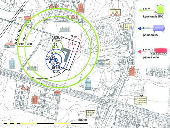
Hazardous areas (thermal radiation/pressure/toxicity and flammable area) as circles on a map and as a function of distance shown in the table. The map must clearly show the sensitive targets around the site.
A written impact assessment in respect to external sites (more details in chapter 5).
Summary
Publicity of the impact analysis
Pursuant to sections 24.7 and 24.8 of the Act on the Openness of Government Activities (621/1999), detailed impact analysis data can be classified as confidential. Such data includes detailed process descriptions, equipment information, PI diagrams, layout drawings and information on security systems (preparedness). However, hazardous chemicals, general descriptions of accident scenarios and initial data are public, along with the hazardous areas (impact area maps).
Impact areas and assessment criteria
The result of the impact analysis must include the distances for the following impact areas:
Flammable 50% and 100% LEL range measured at leakage point
Thermal radiation intensities at 3 kW/m2, 5 kW/m2 and 8 kW/m2
For BLEVE, the thermal dose unit (TDU) and peak pressure of the fireball
peak pressures at 0.05 barg, 0.15 barg and 0.3 barg
chemical concentrations at AEGL-2 (10 and 30 min) and AEGL-3 (10 and 30 min). If the chemical does not have AEGL values, it is possible to use ERPG-3 and IDLH or equivalent values, making sure that exposure times do not deviate from the AEGL values.
By default, the impacts are estimated at a height of 1.5–2 metres from the ground level. If grounds spills spread significantly further, there are tall buildings in the environment or the model indicates that the vapour clouds will spread higher, the results must be examined at heights relevant to these sites.
In addition to the impact areas, the safety assessment of the plant’s site must also take the number of people at the exposed site, exposure time, the functional capacity of the persons, the ability to train for the event and self-protection, operational capability of the rescue department, and other similar factors into account.
The criteria for the intensity of thermal radiation are listed in Table 1.
Table 1. Criteria for the intensity of thermal radiation
Intensity of thermal radiation kW/m2
Impact
Allowed functions
12-15
Plant and buildings may ignite
Fireproof or fire-protected buildings
8
Risk of fire spreading increases, flammable materials can ignite or break
Buildings, sites that propagate the fire
Maximum designed intensity of thermal radiation at the property line
5
Human activity becomes difficult, causes burns quickly
Buildings and other sites with people in them
3
Long-term exposure causes burns
Building exits and escape routes
1,5
Unpleasant heat
Difficult to evacuate buildings or high population density outside the plant
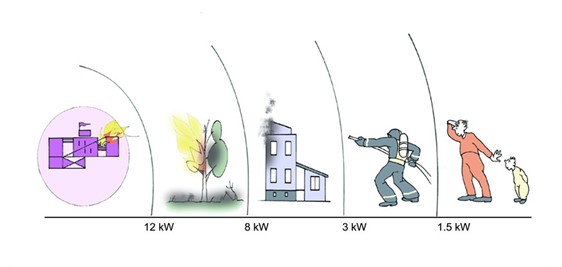
Figure 2: Effects of thermal radiation. For more examples of the effects of different levels of thermal radiation, see Casal, J. (2008) Evaluation of the Effects and Consequences of Major Accidents in Industrial Plants. Industrial Safety Series, Elsevier, Amsterdam
When assessing personal safety, it may also be justified to examine the thermal dose units. The following can be used as guidance values:
intensity of thermal radiation at 3 kW/m2 for more than 2 minutes causes irreversible effects (600 TDU)
intensity of thermal radiation at 5 kW/m2 for more than 2 minutes is lethal (1000 TDU)
Technical means such as firewalls, radiation protection, or fireproof materials are usually acceptable protective layers for reducing the impacts of thermal radiation. The intensity of thermal radiation and the thermal doses can be used to assess the functions and safety distances at the production plant site. Higher thermal radiation intensities are allowed inside the plant than outside.
The criteria for assessing pressure impacts (peak overpressure) are listed in Table 2.
Table 2. Assessment criteria for pressure impacts
Peak overpressure kPa (bar)
Impact
Allowed functions
30 (0,3)
Building collapse, spread of accident
Production equipment and structures
15 (0,15)
Damage to buildings, risk of injury
Buildings and structures less susceptible to pressure impacts or other justified reason to accept overpressure
10 (0,1)
Maximum designed peak overpressure at the property line
5 (0,05)
Minor risk of injury, no more than minor damage to buildings, windows break
Buildings and areas with people in them as a rule
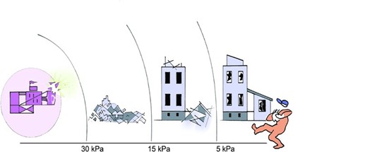
Various obstacles or topography do not significantly protect against the effects of a pressure wave. The only protection from a pressure wave is a sufficient distance or a building designed to be explosion-proof. When designing pressure-resistant structures, other factors (e.g. overpressure and underpressure impulse, reflection waves) than overpressure must also be considered.
Figure 3: Impacts of a pressure wave.
4.3.1 Debris
An explosion, especially a BLEVE, can scatter debris into the environment that cause damage. The trajectories of the debris depend on the launch speeds/angles and the size of the pieces (air resistance/gravity). There are theoretical models and statistical analyses for modelling debris, based on blasting tests. It is necessary to consider the hazard caused by debris when siting and/or protecting adjacent buildings, but they are not required in the model. The OVA guidelines published by the Finnish Institute of Occupational Health provide indicative hazard areas and safety distance radii.
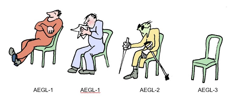
4.4 Health impacts (Government Decree 856/2012, section 8)
AEGL-3 and -2 values are used to assess health impacts. These are chemical-specific thresholds (concentrations) at which a human may be subject to:
life-threatening effects (AEGL-3); or
serious health effects and loss of normal functional capacity (AEGL-2)
if the exposure continues for a specified period of time. Minor effects, such as various irritation symptoms or odour pollution, are not required to be modelled.
AEGL-2 applies to areas with large numbers of people on a regular basis (shopping centres, blocks of flats, sports halls, etc.) or areas with targets where people are expected to have reduced capability for self-protection. These targets include care institutions, schools and daycare centres.
AEGL-3 is used for other less sensitive targets or areas, as these targets have a better chance of taking cover inside or leaving the area of the vapour cloud, thus avoiding serious health effects.
As a rule, the exposure period that is used is 30 minutes, but in short-term accidents or situations where the exposed population is able to take cover or leave, it is possible to use a shorter period of 10 minutes. A short-term accident may be, for example, a breakdown of an individual chemical device or transport package. In very short leakages of no more than some tens of seconds, AEGL values easily overestimate the health effect, as they are defined for exposures of at least 10 minutes. In these situations, other criteria than AEGL that better describe the relationship between exposure and adverse health effects can be used based on risk assessment and the discretion of Tukes.
The most effective way to protect against toxic gas leaks is to go indoors, which significantly reduces exposure. Buildings and proper ventilation measures can further reduce the penetration of gas from outside to indoors. People at work are usually in a better position to protect themselves, because they can, for example, practise taking cover and how to act in a gas hazard in advance. As a result, workplaces are considered less sensitive than public or customer facilities.
4.5 Safety distances to other targets
Sections 9–11 of the Chemical Safety Decree deal with the siting of a production plant in relation to natural preserves, Natura areas and recreational sites, groundwater areas, key functions and sites essential to society, such as electricity lines, main transport routes or sites of cultural history. Potential accidents may not cause harm to the aforementioned targets or activities in respect to their significance or natural values. More detailed information on the siting of a plant in respect to these targets is compiled in Annex 4.
As a rule, the safety distance from a wind turbine to a production plant is 600 m. If the distance is shorter, a report is required on the safe siting of the wind turbine. This report must consider, for example, the fall of the tower, detaching blades, the accumulation and detachment of ice, and fire.
4.5.1 Production plants in close proximity
The domino effect is an event where an accident causes a new accident at another production plant. Explosions and fires are considered to have domino effects, but the spread of toxic gases is not. For example, debris from an explosion may puncture a container in a neighbouring plant, or a tank fire may spread to the chemical storage of the neighbouring plant. Tukes has defined areas where the risk of accidents may grow due to the proximity of other production plants. Areas with a domino effect have usually come about when the area was originally wholly owned by one operator, but its activities have later been divided into several companies. In Finland, domino areas are located in industrial parks and port storage areas.
When there are plans to site a new production plant or an extension next to an existing plant, it is necessary to take the accident impacts of both plants into account in the siting to prevent the spread of an accident. The impact areas of accidents at different plants can be compiled on the same map, for example.
Climate change may intensify extreme natural phenomena such as floods, heavy rainfall and snowfall, storm winds and wildfires and make their occurrence more intense and frequent. Extreme weather can cause accidents in industrial plants – there is even a specific term for this: Natural hazard triggered technological accidents (Natech, Natural hazard triggered technological accident; Chemical accident prevention, preparedness and response | OECD, Luonnon ääri-ilmiöihin liittyvien vaarojen arviointi prosessilaitoksilla). It is necessary to take natech hazards into account in the siting and design of production plants, such as the foundations of tanks and buildings or the support and protective structures of equipment.
Natural phenomena can affect the accident hazards of the plant in various ways:
safety systems and structures may be impaired or become nonfunctional
goods and support systems and equipment may become nonfunctional
instructions and procedures for emergencies may not work properly
rescue operations are impaired or completely prevented
natural phenomena can cause a domino effect in industrial areas with many separate actors
some natural phenomena may impact large areas and cause several simultaneous accidents
Awareness of weather and natural conditions is part of the plant site selection and planning.
4.6 Siting in the production plant area
Internal safety distances at the plant serve to prevent accidents from spreading from one process area to another or from equipment with a high risk of leakage to other critical functions. The layout design includes the necessary road connections, buildings, safety basins and various support functions, such as transformers, firewater pumping stations or the siting of firefighting waste water collection systems.
Sufficient internal safety distances make the plant inherently safer and more crisis-resilient by limiting the spread of accidents. Internal safety distances are determined with a similar impact analysis as external safety distances. To assess the impacts of pressure and thermal radiation, it is possible to use the criteria of this guide (permitted overpressure and thermal intensity values) to assess them, considering the different ways to mitigate the impacts within the plant area with various structural or other protective solutions.
The following general design principles and risk management solutions are used in the plant design:
The largest chemical stocks must be placed outside process areas
At least two approach directions for rescue routes
Traffic is directed outed a safe distance away from hazardous chemical equipment
Traffic routes at the plant area must consider winter conditions
Equipment is sited in safety basins or other leak control structures
Sufficient free space is left around the equipment (e.g. direction of discharge, previous equipment, tanks and their siting conditions, maintenance, pressure and thermal effects)
Prevent the accumulation of flammable gases in cavities or confined spaces
Remove additional sources of ignition (e.g. equipment that may be placed elsewhere)
Use automatic valves where rapid separation of the leakage point is required
Take any areas or facilities required for downtime and maintenance work at the plant into account
4.6.1 Design principles for the siting of pressure equipment
The site for pressure equipment must be chosen in a way that it can be appropriately used, serviced and inspected
The site has been chosen with general safety and that of its users and other personnel in mind in a way that, in the case of damage, the discharge of pressure into the area is as limited as possible and in the direction of the least danger.
When siting equipment, conditions like external temperatures must also be taken into account.
Damage to load-bearing structures caused by a pressure discharge must be limited by making a sufficient part of the other surrounding structures as lightweight as possible.
Walls or intermediate floors dimensioned for a pressure load of less than 1 kN/m2 are considered lightweight structures.
Survey of the surrounding facilities. If a pressure tank is sited in a separate space from the rest of the building, both adjacent and permanent work or living spaces above and below it must be protected with firm walls and intermediate floors.
Walls and intermediate floors that are dimensioned for a pressure load of at least 5 kN/m2 are considered firm.
If a pressure tank is sited in a location with forklift or other traffic, the tank must be protected witha protective fence or a collision shield. .
The location of a boiler room’s weak wall or corner must be determined. It must not be located close to the emergency escape routes and the hazard areas must be indicated.
Especially when siting outdoors, make sure that the pressure discharge is not directed to a building from the doors or windows. Also account for the location of the equipment in relation to the neighbours and the property line
For more information on the siting of pressure equipment, see PSK standard PSK4902
4.7 Summary of permissible impact at different types of targets
Target
Maximum allowed thermal radiation (kW/m2)
Maximum peak overpressure (barg)
Maximum gas concentration
Debris
Sensitive, difficult-to-evacuate targets
1.5
0,05
AEGL-2 (30 min)
Not allowed
Sensitive targets
3
0,05
AEGL-2 (30 min)
Not allowed
Dense residential areas with blocks of flats
3
0,05
AEGL-2 (30 min)
Single-family houses
3
0,05
AEGL-3 (30 min)
Offices
3
0,05
AEGL-3 (10/30 min)
Production plants
5
0,15 (if buildings are resilient to this level)
AEGL-3 (10/30 min)
Monuments and cultural heritage sites
3
0,15
No orders
Not allowed
Critical infrastructure
Excessive disruption to critical infrastructure is not allowed
Natural values
Permanent damage to critical natural value is not allowed
Other hazardous targets
Domino effects must not occur
5 Safety distances for certain chemicals
This chapter contains tables with sufficient safety distances to external sites for flammable liquids, oxygen, LPG, ammonia in refrigeration plants, and other substances hazardous to health or the environment. There are specific safety distance requirements given in regulations for explosive and liquefied petroleum gas targets and natural gas pipelines.
The general principles of the Chemical Safety Regulation must be considered in the siting of a chemical storage facility (container, silo, bulk storage or similar). According to section 12 of the Chemical Safety Decree, the distance of a chemical storage from the production plant's property line must always be at least 5 metres.
5.1 Flammable liquids
Flammable liquid means a liquid chemical with a flash point no higher than 100 °C. The safety distances for flammable liquid stores must be determined based on the thermal radiation of a fire in accordance with section 13 of the Chemical Safety Decree.
Standards SFS 3350 (Storage sites for flammable liquid chemicals and chemical processing sites therein) and SFS 3353 (Flammable chemical production facilities) set forth different safety distances to neighbouring properties, traffic lanes and other similar targets. These standards can be used to determine safety distances. SFS 3350 applies when the total volume of flammable liquids is at least 500 m3.
Above-ground storage tanks of flammable liquids, as well as bulk and container stores not covered by the standard are sited in accordance with Table 3.
Table 3. Safety distances between above-ground storage tanks for flammable liquids and bulk or container stores.
Storage volume or tank size (m3)
Distance 1 (m) distance to buildings and other targets that a fire may ignite
Distance 2 (m) distance to sensitive targets
1 ≤ V < 10
5
10
10 ≤ V < 100
10
20
100 ≤ V < 200
15
25
The safety distance is calculated from the tank shell or, if the tank is placed in a safety basin (barrier), from the edge of the basin. Safety distances shorter than the distances given here may be applied if it is possible to demonstrate that the same effective protection can be achieved in the event of an accident, for example with protective walls, water spraying or other similar solutions. Note: The minimum distance to the property line with above-ground tanks and outdoor bulk/container storages is 5 metres (Government Decree 856/2012, section 12). Oil tanks connected to an oil heating system must comply with the minimum distances specified in the legislation.
5.2 Oxygen
Siting of oxidising chemical tanks, such as oxygen, is covered in section 15 of the Chemical Safety Decree. The main principle is that a leak of an oxidising chemical must not cause a combustible material to ignite.
As oxygen concentrations increase, there is a danger that combustible materials will ignite more easily, burn more intensely and lead to a more rapid spread of the fire (fires and burning clothes). Liquid oxygen spills may cause frostbite. Pressurised oxygen can even ignite metal, e.g. when a valve is opened. A BLEVE is also a possibility for liquefied oxygen tanks.
The European Industrial Gas Association (EIGA) estimates that oxygen concentrations above 23.5% pose a significant risk of fire. It can make clothes, for example, more easily flammable and burn vigorously. The cold vapour from a pool of liquid oxygen causes a visible fog cloud due to the condensation.
Oxygen tanks may not be sited on the walls of buildings that are made of combustible material, near combustible material, or sources of ignition. Further instructions for operators that use, and store oxygen are available in the Tukes guide on the safe handling and storage of oxygen (Finnish).
The requirements of pressure equipment legislation on the siting of pressure equipment must be considered when siting a tank.
Table 4. Safety distances for liquid oxygen
Storage volume or tank size (m3)
Distance to sensitive targets and locations where an oxygen leak can pose a significant fire risk (e.g. combustible material stores, electrical/charging stations)
1 ≤ V < 10
15
10 ≤ V < 20
25
20 ≤ V < 35
40
The safety distances of larger containers are determined with a case-by-case impact analysis, if one is necessary.
5.3 LPG
5.3.1 Facilities that use LPG
The safety distance requirements for liquefied petroleum gas have been examined in the sub-group of the gas division of the Advisory Board on Safety Technology (TENK) (Nessu working group). The group chose the seven following accident scenarios to examine. The chosen scenarios are a comprehensive description of the hazards at a typical LPG plant. If another leak scenario that may cause significant accidental impacts is discovered in the risk analysis, it must be considered in the siting of the plant.
LPG tanks of over 5 tonnes must be primarily sited underground or under soil cover (858/2012, section 8). Soil cover will protect the tank from external thermal radiation and collisions. If an LPG tank of over 5 tonnes is to be placed on the above-ground, the permit application must indicate how an adequate level of safety is achieved (e.g. how the container is protected against collisions and thermal radiation, see LPG guidelines) and examine the impacts of a BLEVE explosion in the environment of the tank’s site.
The Nessu working group used the ALOHA programme to model the impacts of the accident scenarios. In all scenarios, the impact areas of the accidents were approximately 10–15 metres, including the size of the flammable vapour cloud caused by a leak (LEL 100%), the thermal radiation of the flash-out caused by an igniting gas cloud (3 kW/m2), and the thermal radiation of the jet fire at the leak point (3 kW/m2).
Based on the modelling, the safety distance is 15 metres under the following boundary conditions. The safety distance is examined from the following points of view.
The LPG is evaporated and delivered to the equipment in gaseous form.
The maximum size of the LPG pipe leading to the evaporator is DN25.
The container on the tanker vehicle is equipped with an overflow valve and the storage tank is equipped with a check valve to stop leakage when the discharge hose is disconnected or broken.
The size of the flammable vapour cloud area (LEL 100%) is unobstructed and therefore the ignition of the cloud cannot cause significant pressure effects (“closed space explosion”), see section 3.2.B6. The Nessu working group recommends against siting emission sources between two nearby buildings.
There is no fire load next to the above-ground tank, and it cannot be exposed to thermal radiation from the fire of nearby LPG or other equipment, pipelines, etc. The position of the LPG container is chosen in a way that it is protected against vehicle collisions and falling objects. Primarily, the tank is protected with a soil cover or by placing it underground.
Information on the model:
The model was prepared with ALOHA. The accident scenarios are relatively simple, and the group estimated that ALOHA will produce reliable results in these cases. Impact distances have also been compared with the distances used in Germany, the Netherlands and Sweden to ensure reliability.
The models made use of weather type 5D (wind speed 5 m/s, stability neutral).
The ignition time was selected for the moment when the modelling indicates the largest possible effect (the maximum volume of flammable gas-air mixture).
Accident scenarios to be considered when siting an LPG plant:
Scenario 1: Damage to or detachment of the tank vehicle’s discharge hose from the storage tank's filling connector. Gas leak from the discharge hose and tank vehicle’s pipe ignites in a flash-out.
Point of observation: LPG tank filling connector
Scenario 2: Damage to a pipe or equipment that contains LPG in the tank’s maintenance well. The size of the leak opening is 10% of the cross-sectional area of the pipe, the leakage volume is small enough that the tank’s overflow valve does not close. The leaked gas ignites in a flash-out. The fire continues as a jet flame at the point of leakage.
Point of observation: Tank maintenance well (if the tank’s filling connections are located in the maintenance well, scenario 2 can be considered to be included in the safety distances of scenario 1)
Scenario 3: Damage to a pipe that contains LPG upon rising to a building wall or breakdown of the evaporator. The size of the leak opening is 10% of the cross-sectional area of the pipe, the leakage volume is small enough that the tank’s overflow valve does not close. The leaked gas ignites in a flash-out. The fire continues as a jet flame at the point of leakage.
Point of observation: LPG pipeline rise point (if the pipeline's rise point is located away from the evaporator, the safety distances must be examined from both the pipeline rise point and the evaporator)
Scenario 4: Pressure increase in the post-evaporator piping that results in the safety valve opening. LPG is discharged from the outlet pipe of the evaporator's safety valve. The leaked gas ignites in a flash-out. The fire continues as a jet flame at the point of leakage.
Point of observation: End of the evaporator safety valve's outlet pipe
This scenario can be ignored if a device is used that is independent of the pressure reducing valve, e.g. a safety shut-off valve (see Figure 21a of SFS 5987) or a similar function that stops the flow of LPG to the pipe after the evaporator when the pressure rises above the safety limit.
Scenario 5: The tank is over capacity; LPG is discharged from the tank’s safety valve. The safety valve opens momentarily. The leaked gas ignites in a flash-out.
Point of observation: End of the tank safety valve's outlet pipe
The scenario can be ignored if:
the tank has soil cover or is underground;
the tank has a gas return port that is used to connect the tank vehicle and gas tank's volume during filling.
Scenario 6: Leak at pump centre: Damage to the pipe or hose on the pressure side of the pump, breakage of the pump, size of the leakage opening is 10% of the cross-sectional area of the pipe or hose. The leaked gas ignites in a flash-out. The fire continues as a jet flame at the point of leakage.
Point of observation: Connection on the pump’s pressure side
Scenario 7: Sudden rise in pressure in an above-ground liquid gas tank with 5 tonnes of gas content and rupture thereof (BLEVE).
The scenario can be ignored if:
the liquid gas tank has soil cover or is underground;
the above-ground tank contains less than 5 tonnes of LPG.
Table 5 contains a demonstration of how thermal radiation and pressure impact are taken into account in the siting of LPG equipment in relation to different sites. The minimum safety distances laid down in the LPG regulation (Government Decree 858/2012, section 33) must be taken into account in siting. The minimum distances given in the LPG regulation are calculated from the tank filling connector. If the estimated accident impact distances exceed the minimum distances given in the table below, these must be observed.
Table 5. Assessment of accident impacts: Soil-covered and underground tanks.
Target that may be impacted by the accident
Maximum permissible impact
Minimum distance according to Government Decree 858/2012 (m)
Pressure (kPa)
Thermal radiation (kW/m2)
LPG 5–50 tonnes
LPG 50–200 tonnes
Neighbouring property line
10
8
5
10
Public lane of traffic
10
8
5
10
Transport hubs
5
5
15
30
Production plant buildings, equipment, structures, or other targets that may contribute to the spread of fire
15
8
5
10
Production plant buildings or parts thereof with people in them (e.g. workplace cafeteria, office building) and where the accident impacts may extend inside the buildings
5
5
The decree does not set a minimum distance for this target. Without a separate accident model, use a minimum distance of 10 m.
Plant escape routes
5
3
The decree does not set a minimum distance for this target. Without a separate accident model, use a minimum distance of 15 m.
Single-family houses not on the property (row and detached houses)
5
3
15
30
Schools, hotels, blocks of flats, hypermarkets, hotel accommodation and other buildings intended for large crowds
5
3
30
50
Care facilities and other similar targets that are slow to evacuate
5
1,5
100
100
Table 6 contains a demonstration of how thermal radiation and pressure impact are taken into account in the siting of LPG equipment in relation to different sites. The minimum safety distances laid down in the LPG regulation (Government Decree 858/2012, section 26) must be taken into account in siting. The minimum distances given in the LPG regulation are considered from the exterior surface of the tank. If the estimated accident impact distances exceed the minimum distances given in the table below, these must be observed.
Table 6. Assessment of accident impacts: Above-ground tanks.
Target that may be impacted by the accident
Maximum permissible impact
Minimum distance according to Government Decree 858/2012 (m)
Pressure (kPa)
Thermal radiation (kW/m2)
LPG max. 5 tonnes
LPG 5–50 tonnes
Neighbouring property line
10
8
5
10
Public lane of traffic
10
8
5
10
Transport hubs
5
5
15
35
Production plant buildings, equipment, structures, or other targets that may contribute to the spread of fire
15
8
5
10
Production plant buildings or parts thereof with people in them (e.g. workplace cafeteria, office building) and where the accident impacts may extend inside the buildings
5
5
The decree does not set a minimum distance for this target. Without a separate accident model, use a minimum distance of 10 m.
Plant escape routes
5
3
The decree does not set a minimum distance for this target. Without a separate accident model, use a minimum distance of 15 m.
Single-family houses not on the property (row and detached houses)
5
3
15
35
Schools, hotels, blocks of flats, hypermarkets, hotel accommodation and other buildings intended for large crowds
5
3
50
100
Care facilities and other similar targets that are slow to evacuate
5
1,5
The decree does not set a minimum distance for this target. Without a separate accident model, use a minimum distance of 100 m (if the top of the tank is protected from jet flames)
300
5.3.2 LPG bottle and container stores
No more than 50 tonnes of LPG
For stores that contain up to 50 tonnes of LPG (all bottle/container sizes), the minimum distances from the property line of another party, public traffic lanes, external buildings, and gathering places are determined in accordance with the LPG regulation (858/2012, section 24) (Table 7). As a rule, a separate accident impact model is not required for stores of this size. The minimum distances are counted from the outer edges of the storage area.
Table 7. Outdoor storage of LPG bottles and containers
Amount of LPG
Minimum distance (m)
no more than 1 tonne
3
over 1 tonne but under 5 tonnes
6
over 5 tonnes but no more than 50 tonnes
10
over 50 tonnes
based on hazard assessment
However, a more detailed assessment of the accident hazard and modelling may be necessary in the following cases
LPG storage is large-scale (at least 5 tonnes), there are sensitive targets in the consultation zone of the storage area (The consultation zone for LPG bottle and container storage areas is, as a rule, 300 metres), and/or issues identified in the risk assessment require a more detailed analysis.
If required by a public authority for justified reasons.
If the safety distance for smaller LPG storage areas is determined through modelling, the following section must be observed.
Over 50 tonnes of LPG
The safety distance for storage areas of LPG bottles and containers which contain more than 50 tonnes of LPG must always be estimated through modelling. The safety distance is determined through the following accident scenarios:
Safety valve discharge and ignition of the largest LPG bottle/container or bottles stored in the same cage.
BLEVE of largest bottle/container
The safety distances for different targets are determined in accordance with the criteria in Table 6, in the previous chapter (thermal radiation and pressure effects). In addition, in the safe siting of the storage area, it is necessary to assess the impact caused by a gas bottle explosion (see section 4.3). It is necessary to consider the hazard caused by debris when siting and/or protecting adjacent buildings, but they are not required in the model. As mitigating factors, it is possible to consider the limiting effect of the bottle cages and surrounding structures, among others, in the assessment of debris impacts.
5.4 Ammonia refrigeration plants
Ammonia refrigeration plants refer to the assembly of components of an ammonia-based refrigeration system and the equipment necessary for its operation. Ammonia refrigeration plants are typically used in the food industry, cold and cool storage, and ice rinks and fields. This chapter does not apply to the manufacture or storage of ammonia.
The hazard areas for accidents in ammonia refrigeration plants are assessed based on the health hazard caused by ammonia leakage in accordance with section 16 of the Chemical Safety Decree 865/2012. The plans must also consider the equipment and systems intended for recovering from or limiting the spread of a chemical leak in accordance with section 73 of the Decree.
Ammonia is a colourless, pungent, and highly irritating gas. The hazard statements of ammonia under the CLP regulation are:
H221 Flammable gas. H331 Toxic when inhaled. H314 Causes severe skin burns and eye damage. H400 Highly toxic to aquatic life.
Ammonia typically leaks into the environment through the refrigeration plant’s safety devices or during emergency ventilation. Leaks are caused by breakage or failure of the refrigeration system’s equipment, such as pumps, compressors, tanks, valves or joints. The risk of accidents at an ammonia refrigeration plant depends on both on the amount of ammonia and the make-up of the plant. A large leak may cause respiratory irritation at very large distances, but a serious health hazard is estimated to occur at a maximum distance of 500 metres from a conventional refrigeration plant.
The consultation zone for ammonia refrigeration plants under the supervision of Tukes is typically 500 m, which warrants an examination of land use at this distance from the production plant. Certain ammonia refrigeration plants, such as ones with several separate refrigeration plants in the production area, may also have larger consultation zones.
Various instructions and information on ammonia cold plants are available on the websites of international institutes of refrigeration (iifiir.org and iiar.org) and in a publication of the Finnish Refrigeration Association.
5.4.1 Assessment and modelling of the siting of refrigeration plants of different sizes
Criteria for all plants:
The criteria given in Chapter 4 of this Guide apply to the modelling of the health hazard of ammonia gas. The design principles for refrigeration plants are set in a series of standards, SFS EN 378, which must be complied with for ammonia refrigeration plants of all sizes. An explosion of ammonia gas, spread of liquid ammonia or an ammonia solution into the environment is not required in the modelling if the refrigeration plant has been implemented in accordance with the chemical safety regulations and said set of standards.
All ammonia refrigeration plants require a risk assessment regardless of size. The risk assessment identifies the most significant cases of ammonia leakage and determines the necessary preparedness measures to prevent leaks and reduce the impact. The assessment must take into account the scope and probability of leaks and the sensitivity of the plant's immediate environment. It is necessary to describe the various contingency measures, such as detection systems, automatic safety functions and alarms connected to measurements, and the impact thereof on an identified leak. The gas collection and scrubbing systems installed at the outlets of emergency ventilation for safety valves and engine rooms and similar mitigation equipment are decided based on a risk assessment.
5.4.2 Ammonia refrigeration plants that do not require modelling
Under 100 kg of ammonia
Plants with less than 100 kg of ammonia do not require an official permit. There are no specific safety distance requirements for plants of this size and leak modelling is not required. The siting of the equipment must take into account the requirements of pressure equipment legislation for the siting of pressure equipment and the requirements of the SFS EN 378 series of standards. Part 1 of the series defines the permitted filling limits for refrigeration machinery in different facilities.
100 kg–10 tonnes of ammonia
As a rule, when the size of the refrigeration plant is under 10 tonnes, modelling is not required if the safety distances of Table 8 are met. Modelling may be required in the following example situations:
There are sensitive targets at under 500 metres from the plant, and the issues raised in the risk assessment require a more detailed assessment.
The refrigeration plant is part of a large-scale production plant under Tukes supervision.
If required by a public authority for justified reasons.
Table 8 sets forth safety distances for two types of plant:
Type A: All equipment, except the condenser and its pipelines, are either in the engine room or in production facilities
Type B: Facilities other than type A
Table 8. Safety distances for ammonia refrigeration plants.
amount of ammonia (t)
Type of plant
Distance 1 (m) distance to buildings outside the plant area that may generally house people
Distance 2 (m) distance to sensitive targets
0,1 ≤ m < 1,5
A and B
25
50
1,5 ≤ m < 3,0
A and B
40
100
3,0 ≤ m < 10
Type A
40
150
Type B
80
250
The distances are calculated from the building or part thereof where the refrigeration centre and its associated equipment are located
The safety distances shorter than what are given in Table 8 can be used applied if a risk assessment and the addition of technical protection solutions can demonstrate a similar protective effect in the event of an accident.
Large refrigeration plants (minimum 10 tonnes of ammonia)
Large refrigeration plants containing at least 10 tonnes of ammonia require a permit from Tukes. The requirements to site these plants are always assessed through an impact analysis that is prepared on a case-by-case basis. The impact analysis and report must be performed in accordance with Chapter 4 of this guide.
Safety distances are determined based on the following scenarios:
The mass flow rate (g/s) of a leak corresponding to the discharge capacity of the largest safety valve of the plant at design pressure and the filling of the selected ammonia circuit. The leakage point is the outlet point of the safety valve, also taking into account its exit direction.
Leakage through emergency ventilation to the engine room floor, forming a large pool of liquid ammonia as the cause of equipment failure. Ammonia vaporises from the pool and is carried outside through emergency ventilation, causing it to spread to the environment. The modelling must take into account the location of the emergency ventilation outlets, the direction of ventilation, and the replacement air that mixes with ammonia.
Due to the risk assessment prepared for the refrigeration plant, a change that significantly increases the number of exposed persons in the consultation zone, additional construction, or other reason found by the authority during the permit process or supervision, the following accident scenarios must also be modelled in addition to the aforementioned events:
Leakage from a hot gas pipe leading to the condenser on an outdoor section. The size of the opening must be 10 % of the cross-sectional area of the largest pipe.
Leakage from an opening in the largest outdoor liquid (or gas-liquid mixture) pipe of ammonia that is 10 % of the cross-sectional area of the largest pipe.
Leakage from an opening in the drainage pipe of the condenser that is 10 % of the cross-sectional area of the largest pipe.
5.5 Other chemicals that are hazardous to health or the environment (liquid or solid)
Section 16 of the Chemical Safety Decree Other storage areas that contain liquid or solid chemicals that are hazardous to health and the environment must be sited in such a way that the chemical cannot spread outside the production plant area in case of a leak. Safety distances must take into account the flue gases generated by the degradation of the chemicals and other reactions during a fire.
Other chemicals that are hazardous to health are typically chemicals that irritate or sensitise the skin, eyes or respiratory tract. Acids and bases are corrosive when concentrated and irritating on skin in a solution. They cause burn-like symptoms on the skin and irritation in the respiratory tract. In an aquatic environment, damage is caused by the changes in acidity. Corrosive chemicals can also react intensely with other substances, causing spills, toxic gases or a fire hazard. As the name implies, chemicals that are hazardous to the environment pose a risk to natural environments.
For chemicals that are hazardous to health and the environment, the most important thing is to prevent them from leaking into the environment and that any leaks can be recovered. Containers and container storage areas of liquid or solid chemicals must be sited in accordance with the safety distances in Table 9.
Distances in following table do not apply to oxidising chemicals, organic peroxides, or chemicals that can form toxic or flammable gases as a result of a reaction
Table 9. Safety distances for other chemicals that are hazardous to health and the environment.
Storage volume or tank size (m3)
Distance 1 (m) distance to buildings outside the plant
Distance 2 (m) distance to sensitive targets
1 ≤ V < 10
5
10
10 ≤ V < 200
10
20
200 ≤ V < 1000
15
30
1000 ≤ V < 6000
20
40
The safety distance is calculated from the edge of the protective basin or barrier. If more than one safety distance can be specified for the chemicals in the tables of this guide, use the greatest possible distance.
ANNEX 1: Demonstration of health, thermal radiation and pressure impacts on a map
ANNEX 2: Limit values for health hazards
AEGL (Acute Emergency Guidance Levels)
On a scale of 1 to 3, AEGL indicates what kind of adverse effects a person may have after a set period of exposure to a particular chemical concentration. The values are intended for the normal population while taking sensitive individuals into account and are thus thought to protect almost everyone.
There are AEGLs for each of the three impact levels for a total of five different exposure periods (10 minutes, 30 minutes, 1 hour, 4 hours and 8 hours).
AEGL-1: Significant discomfort, irritation or certain asymptomatic, non-sensory effects.
AEGL-2: Irreversible or other serious, long-term adverse health effects or reduced ability for rescue.
On a scale of 1 to 3, ERPG indicates what kind of adverse effects a person may have after a 60-minute exposure to a particular chemical concentration. ERPG values do not protect each individual, but hypersensitive individuals may have a reaction to a much lower concentration.
ERPG-1: At the ERPG-2 and ERPG-3 concentrations, the chemical does not pose a health risk, but its presence is noticeably by odour or mild irritation symptoms. ERPG-1 is not available for all chemicals, such as when the sensory detection threshold is higher than the ERPG-2 value of the substance.
ERPG-2: At concentrations below this level, it is estimated that nearly everyone be exposed for one hour without the risk of irreversible or other serious adverse health effects or symptoms that reduce the ability to take cover from exposure. Higher concentrations (ERPG-2, ERPG-3) may include severe eye or respiratory irritation, muscle weakness, damage/disruption of the central nervous system or severe irreversible health effects.
ERPG-3: At concentrations below this level, it is estimated that almost everyone can remain exposed for one hour without life-threatening effect. The risk of death rises at higher concentrations.
IDLH (Immediately Dangerous for Life and Health)
IDLH is the highest concentration to which a healthy worker may be exposed for 30 minutes without irreversible damage to health or injuries that make it difficult to escape.
These values are defined by NIOSH (National Institute for Occupational Safety and Health, USA). IDLH values have been defined for about 400 substances.
ANNEX 3: Weather stability categories
Weather types chosen for modelling:
Neutral weather (D) with wind speed 5 m/s, which is a typical weather in Finland.
Stable weather (F) with wind speed 2 m/s, which is an unfavourable situation for a chemical to spread.
Weather type 5/D represents average conditions in Southern Finland. Weather type 2/F corresponds to the most unfavourable situation for a gas to spread, where it does not mix well with air and the concentration of substances in a moving cloud remain high. These conditions typically occur on a clear night or a bright winter day.
There are many factors to weather conditions that influence the spread of chemicals in the atmosphere, such as wind direction and speed, differences in temperature at different altitudes, and the amount of solar radiation. Atmospheric weather conditions are described in the stability classification, which places different types of weather in their own categories. There are seven of these categories (A-G).
Table: Pasquill Stability Classes.
Surface wind speed (m/s)
Daytime insolation (W/m2)
Nighttime cloud cover (n)
strong >600
moderate 300–600
slight <300
cloudy
0–3
4–7
8
≤2
A
A/B
B
C
F or G*
F
D
2–3
A/B
B
C
C
F
E
D
3–5
B
B/C
C
C
E
D
D
5–6
C
C/D
D
D
D
D
D
>6
C
D
D
D
D
C
D
*stability class G applies when wind speed is below 0.5 m/s
Source for table: Essa K.S.M. (2006) Estimation of Seasonal Atmospheric Stability and Mixing Height by Using Different Schemes. VIII Radiation Physics & Protection Conference, 13-15 November 2006, Beni Sueif – Fayoum, Egypt.
Table. Characteristics of different stability classes
Class
Stability
Description
A
highly unstable
Occurs in light wind, and strong and moderate solar radiation, typically on a sunny afternoon
B
unstable
C
slightly unstable
Occurs in moderate and heavy wind and moderate solar radiation, typically on a windy and sunny summer afternoon. Occurs also in light wind and weak solar radiation such as a sunny autumn afternoon, partly cloudy summer day and a clear summer day when the angle of the sun is 15-30 °
D
neutral
Occurs in cloudy weather, both day and night
E
stable
Occurs at night with light wind and nearly clear weather
ANNEX 4: Siting of a production plant in relation to surrounding targets
A A Nature sites and recreational areas
According to section 9 of the Chemical Safety Decree (VNa 856/2012), the impacts of an accident at a production plant may not cause harm to nature preserves or areas intended for recreational use. In accidents that may affect nature preserves and recreational areas, what’s examined is the protection status of the site or area and the impact of the accident on the protection status and its preservation.
Municipal beaches for the use of the public, for example, are considered recreational areas. For example, a private beach at a cottage plot is not a recreational area in this definition. The protection status of a habitat is assessed based on the range, occurrence, habitat structure and the activity as well as the protected status of the habitat’s characteristic species. Information on a species’ population development, natural range and adequacy of a suitable habitat is used to assess the protection status of the species.
Information on nature sites (section 1 of the Decree) and recreational areas (section 2 of the Decree) is available from the competent Centre for Economic Development, Transport and the Environment (ELY Centre). Distances are also available, for example, in the Finnish National Geoportal Paikkatietoikkuna. Information on Natura 2000 sites can be found, for example, in the SYKE map service. Awareness of why a site is a Natura 2000 site (e.g. habitat type, plant or animal species) is essential for the siting of a plant, to assess the potential impacts on the protection value.
It is not absolutely prohibited to site a production plant in the vicinity of nature sites or recreational areas. When assessing the impacts of an accident, it is important to consider, for example, the extent and duration of the impacts as well as the number of people already in the area or introduced to it through the planned recreational activities, and the possibilities of evacuating the population. It is not possible to provide a general statement on the effect of a concentration of a chemical on an object, as it depends on, for example, the properties of the chemical. For example, if an estimate states that a part of the vegetation area of a Natura site is destroyed because of an accident, it does not necessarily impede the siting of a plant. If it can be expected that the protection value of the site is not adversely impacted, the protection value recovers on its own, or it can be recovered within a reasonable time, it may be possible to accept such a risk.
Water bodies
The impacts of a discharge on the water body depend on the season (ice cover, water stratification) and the prevailing wind and flow conditions, which affect the dilution rate of the discharge. Under ice cover in winter, water circulation and dilution of the discharge are relatively slow compared to the open water season. A substance heavier than water can sink to the bottom and to deeps, where it can destroy the bottom-dwelling fauna. A large acid discharge into a water body may cause it to acidify. Insoluble substances that are lighter than water (e.g. oil) can, even in small quantities, cause harm to recreational use and especially the bird life.
It is necessary to assess the impact of a discharge on water quality, acidity and the aquatic environment. In discharges to water bodies, the impacts on plant and zooplankton, bottom-dwelling fauna and fish must be assessed. In addition to direct impacts, it is also necessary to assess the indirect impacts, such as impacts on biotic communities, fisheries and recreational use. For example, phosphoric acid can cause strong growth in base algae production, turbidity of water and eutrophication of water bodies.
Airborne emissions
It is necessary to assess the potential carriage of airborne emissions (gases, dust) to nature sites or recreational areas. When assessing the impact on a protected site or recreational use, it is essential to assess the nature of the recreational activities, how people there can be warned, or how they can shelter or leave the area.
Impact of emissions on soil
Threshold and guide values have been defined for the concentrations of harmful substances in the soil, which can be used to assess the severity and potential need and scope of soil purification (Government Decree on the Assessment of Soil Pollution and Need for Purification 214/2007). The assessment must consider the quality and porosity of the soil and the quantity and characteristics of the substance entering the soil. It is also possible for the substance to pass to groundwater or water bodies through the soil. The potential impact of emissions on soil acidity may influence the vegetation in the area.
Figure 5. Consideration of the environment in siting a plant.
B Groundwater areas
Section 10 of the Chemical Safety Decree (856/2012) contains provisions on taking the chemical hazard to groundwater into account in the siting of a production plant.
If the production plant is to be sited in a groundwater area, the necessity of the placement must be justified in the permit application/notification. It must also be demonstrated that the placement will not cause harm to groundwater. According to the Environmental Protection Act (527/2014), activities that pose a risk of environmental pollution must, as far as possible, be sited in a way that the activities do not cause pollution or a risk thereof. It must also be possible to prevent said pollution. When assessing the suitability of the site, the nature of the activity, the likelihood of pollution and the risk of accident must be taken into account. It is also necessary to account for the current and future use of the area and its surroundings and the planning regulations concerning the area as well as other possible sites in the area.
When considering the specific and justified reasons referred to in section 18(2) of the Chemical Safety Act (390/2005), whether a production plant can be sited in a groundwater area, it is necessary to take the following factors into account on a case-by-case basis:
importance of the groundwater area for the water supply:
The operator must obtain this information from the ELY Centre or the municipality.
nature and extent of the operation of the production plant, along with the characteristics and quantity of hazardous chemicals to be handled and stored there:
The operator must present these matters in the permit application/notification. A separate assessment of chemicals that may not enter groundwater is not necessary.
structural and technical solutions at the production plant to prevent the introduction of hazardous chemicals into groundwater along with other systems that eliminate the possibility of human activity leading to potential groundwater damage:
soil quality and hydrogeological conditions in the area and the behaviour and effects on the environment of chemicals manufactured, processed and stored in the production plant, and substances that may be produced as a result of an accident pursuant to section 5 of the Chemical Safety Regulation:
The operator must obtain information on the soil quality and hydrogeological conditions. It must assess the risks of the activities and chemicals on soil and groundwater. Chemical properties are used to demonstrate their behaviour in an accident.
Impacts that can reach groundwater depend on the properties and quantity of the chemical entering the soil. The structure of the soil and bedrock affect the rate at which the chemical spreads in the soil. Groundwater level (varies by year and season) affects the speed at which a chemical reaches groundwater. After entering groundwater, the spread of a chemical in the water depends on the flow conditions and use of groundwater. Annex I to the Government Decree amending the Decree on Substances Dangerous and Harmful to the Aquatic Environment (342/2009) lists substances or groups of substances that may not be discharged into groundwater.
need for transport related to the production plant’s operation and the impacts of any transport-related damage and accidents on groundwater in the surrounding area.
Assessment of the transport risk can be limited to the yard area of the production plant. The operator must assess the impact of transport-related activities, such as tank filling, on groundwater.
Groundwater contamination may be caused by substances that do not occur naturally or only occur at very low concentrations in groundwater and groundwater deposits. The most harmful chemicals are ones that are hazardous to the environment and health, such as many metal compounds and solvents. Many substances that are considered less hazardous, such as road salt and fertilisers, can also cause contamination. The impacts of an accident on groundwater may only become apparent after decades have passed. Gaseous and insoluble chemicals (e.g. propane/butane) are not thought to pose a hazard to groundwater.
Information on groundwater areas
Important and other groundwater areas suitable for the water supply have been surveyed and defined by the environmental administration. Groundwater area maps show the boundaries of the groundwater areas, groundwater formation areas and possible protected areas Ymparisto > Pohjavesialueet (in Finnish).
C Infrastructure
According to section 11 of the Chemical Safety Decree (856/2012), an accident at a production plant must not interfere with functions that are essential for communities, such as main transport routes, energy and water supply systems and waste management, or permanently damage sites with cultural and historical importance.
Figure 6: Key functions and targets for communities that must be considered in the siting of a production plant.
Main transport routes
Regarding main transport routes in relation to the siting of a production plant, it is necessary to consider thermal radiation or pressure effects of a possible accident at the plant. Also make sure that the health hazard caused by chemicals does not extend to main transport routes in a way that may cause a significant traffic disruption, such as closing of roads.
When assessing a significant disruption of traffic caused by an accident, it is advisable to consider the proximity and usability of the potential alternate route during the accident. The maximum levels of thermal radiation and pressure below apply to the siting of a plant in relation to road traffic.
Table 9: The maximum levels of thermal radiation and pressure for the siting of a plant in relation to road traffic.
Road classification
Maximum allowed intensity of thermal radiation kW/m²
Maximum allowed frontal pressure (kPa)
Highways and transport hubs
5
5
Main roads
5
10
Other roads
8
15
Railways
Railways with national significance in detailed plans include railways on the main railway network, railways that lead to official border crossings, winter harbours, nationally significant travel centres and freight terminals, and the metro in the Helsinki Metropolitan Area. (Application of national land use targets in detailed planning.)
The spread of a railway disturbance and its consequences differ from disturbances in other traffic. The impact area of a railway disruption may be very large due to its multiplier effects. However, a disruption may impact only one train if the operating time, location, or both are sufficiently quiet.
Fire-fighting on or near the railway area may lead to interruptions in rail traffic, for example. In such a case, the police or the rescue authority may request local traffic control to stop the traffic in the requested area or on the tracks.
Energy and water supply and waste management
When siting a plant, what must be considered regarding energy and water supply and waste management is the prevention of a significant disturbance to said functions from thermal radiation or pressure effects (including spills) of a potential accident or the health hazard caused by chemicals.
Siting of the plant must consider the impacts of potential accidents (thermal radiation or pressure effects) on overhead lines, transformers and switchgear of the main power transmission network, as well as the safety distance required for a rescue operation in the vicinity of overhead lines. The impacts of an accident may not damage telecommunications, radio masts or other base stations or cause some other serious disruption.
Buildings, structures and parks or similar sites with cultural and historical significance and sites protected by the Antiquities Act
Buildings, structures and parks of cultural and historical significance refer to the built cultural environment, i.e. building heritage, which is preserved by various means. Further information on protected sites is available in the service of the National Board of Antiquities: Kulttuuriympäristön palveluikkuna (kyppi.fi)
Buildings, structures, parks and monuments of cultural and historical significance may be damaged permanently or in the long-term mainly as a result of a fire or explosion. Parks of cultural and historical significance may also be damaged as a result of a discharge of hazardous chemicals into the environment.
Possible damage to the site is examined after assessing the magnitude of thermal radiation and the pressure effects. The same applies to the assessment of a chemical hazard to the environment.