Description: This guide presents hydrogen production, transmission and distribution methods and safe solutions for them.
Target group: Operators
Date: 23 January 2024
Hydrogen has long been produced and used as an industrial chemical. What is new, however, is the use of hydrogen as a transport fuel and for energy production, as well as the large-scale storage of hydrogen. Hydrogen production and use are increasing at an accelerating pace globally with the need for carbon-neutral energy. In Finland, progress is being made in the design of hydrogen production plants, the distribution network and distribution stations. This has highlighted the need to compile procedures and policies for safe hydrogen production and distribution. This guide presents hydrogen production, transmission and distribution methods and safe solutions for them.
Finland has no separate legislation for hydrogen, but hydrogen is considered a hazardous chemical like other flammable gases. However, because of the special properties of hydrogen, there is a need to align interpretations of the legislation to meet the needs of the hydrogen economy.
Because of its reactivity, hydrogen does not occur in nature as a pure substance, but only in compounds. The properties of hydrogen also give rise to the greatest risks it poses, namely fire and explosion hazards. Because of its small atomic size, hydrogen leaks easily and can cause embrittlement when penetrating a material. Reactivity causes hydrogen to form an explosive air-gas mixture, even at a low concentration. Ignition is more likely, and the pressure impacts of explosions are greater, than with other commonly used combustible compounds.
The purpose of this guide is to provide basic information about hydrogen and its hazards and specific properties to be taken into account in the production and use of hydrogen. The aim is also to clarify the regulations concerning the location of hydrogen plants and distribution stations and to present safety aspects to be taken into account in the design process. The guide focuses on the production and use of hydrogen. Transport and its safety requirements, for example, are not addressed in this guide.
1 Hydrogen as a chemical
Hydrogen is an odourless, colourless and highly flammable gas. Hydrogen is not toxic. Because it is highly volatile and lighter than air, hydrogen does not persist in the aquatic environment for long periods or cause pollution in soil or water bodies. However, at high concentrations, hydrogen gas can cause sudden suffocation. Hydrogen can be odorised, but this is not done in practice because fragrances often need to be removed as impurities when using hydrogen. When combined with oxygen or air and ignited, the mixture releases a large amount of thermal energy. Because hydrogen is light, it blends well with air, but also dilutes quickly. In liquid form, it needs cooling to prevent gasification. The boiling point of hydrogen is -253 °C.
At atmospheric pressure, the ignition limit for the mixture of hydrogen and air is between 4% and 75% by volume. Ignition limits are presented in % by volume (vol%), which indicates the amount of combustible material in the gas-air mixture. Concentrations are indicated at normal pressure and at 20 °C. Below the ignition limit, the mixture is too lean to ignite, and above it, it is too rich.
The ignition energy required for hydrogen is low (0.017 mJ), meaning even a small spark ignites it. The lowest auto-ignition energy is achieved with a 30 vol% mixture. The auto-ignition temperature of hydrogen is 560 °C. High-pressure hydrogen can ignite on its own, as it can reach that temperature.
Hydrogen is an indirect greenhouse gas. Hydrogen reacts very sensitively with hydroxyl radicals (OH) in the atmosphere. The reduction of hydroxyl radicals in the atmosphere affects the persistence of methane, for example. Another consequence of hydrogen’s reaction with hydroxyl radicals is that the proton (H) generated as a reaction product reacts with atmospheric oxygen to form the peroxide radical (HO2), which leads to an increase in the amount of nitrogen oxides (NOx) in the atmosphere. The escape of hydrogen into the air thus increases the concentration of methane and nitrogen oxides in the atmosphere and contributes to global warming.
The molecular size of hydrogen is extremely small, allowing it to penetrate even small gaps. This increases the chances of hydrogen leaks from joints, increasing the likelihood of explosion hazards. For the same reason, hydrogen can penetrate materials, causing hydrogen embrittlement. This occurs when hydrogen diffuses into the material, forming bubbles. The pressure of the bubbles on the structure of the material weakens its strength.
Hydrogen and natural gas may be used as alternative fuels in the future, so it is essential to identify the differences between these chemicals. Table 1 below presents the characteristics of hydrogen and natural gas (CH4) and their differences.
Hydrogen (H2)
Natural gas (CH4)
Hydrogen
Molar mass [g/mol]
2.02
16.04
is markedly lighter
Density (20 °C; 1,013 bar) [kg/m3]
0.08375
0.72
is markedly lighter
Buoyancy in air
14 times lighter
4 times lighter
is markedly lighter
Molecular size
is markedly smaller
Diffusion coefficient in air NTP [cm2/s]
0.61
0.16
Mixes with air faster
Melting or freezing point [°C]
-259
-182
-
Boiling point [°C]
-253
-162
-
Minimum ignition energy in air [mJ]
0.017
0.3
is markedly more flammable
Laminar burning rate [m/s]
2.7
0.4
is considerably more reactive
Self-ignition point [°C]
560
650
-
Flammable range, concentration in air [vol%]
4-75
5-17
has a significantly wider flammable range
Hazard classification
very highly flammable gas
very highly flammable gas
the hazard classification is the same as that of natural gas
Explosion range [% vol.]
18-59
6-14
has a significantly wider explosion range
Lower heating value [MJ/kg]
120
49
has a higher calorific value
Detonation ignition energy [g TNT]
1
1,000
is much more sensitive to detonation
Physical form
colourless, odourless gas
colourless, odourless gas
is less noticeable
Other properties
colourless, poorly visible flame
visible flame, usually bluish
is less noticeable
Hajustus
no fragrances
strong, added fragrance
is less noticeable
Table 1. Comparison of the characteristics of hydrogen and natural gas
2 Hydrogen applications
Hydrogen can be used as a fuel in internal combustion engines or fuel cells or as an energy carrier.
The major applications of hydrogen are the production of methane or ammonia (Haber-Bosch process), the production of various other chemicals, and the production and processing of fossil fuels (hydrocracking). Hydrogen is also used in the manufacture of glass and electronics and as a refrigerant. Hydrogen can also be used to produce fossil-free steel when the iron ore concentrate is reduced with hydrogen.
2.1 Fuel cell
Hydrogen can be converted into electricity in fuel cells. For example, fuel cells are used as stationary sources of electricity or in transport vehicles to provide electricity to an electric motor.
Fuel cells have the advantage of being emission-free and reliable during power outages, for example. The reaction in the fuel cell (H2 + ½O2 --> H2O + e-) requires a catalyst. Platinum is typically used as a catalyst. The high cost of the catalyst significantly increases the cost of the fuel cell.
2.2 Hydrogen reduction in steel production
Hydrogen can be used in the production of steel. In shaft furnace technology, iron oxide pellets are placed in a 950-degree furnace. Hydrogen gas is fed into the furnace from the bottom, and it reacts with oxygen in the ore pellets to form water vapour. The product coming out of the furnace is called sponge iron. The pellets retain their shape in the furnace, but they are porous as a result of the oxygen being removed.
3 Hydrogen production
Hydrogen does not appear as a hydrogen molecule in normal conditions but is bound in compounds such as water and hydrocarbons. To use hydrogen, it must therefore be separated in some way from these compounds. Hydrogen production is thus always an energy-consuming process.
There are several hydrogen extraction or production methods. At the time of this guide’s publication, the most common hydrogen production method worldwide is steam reforming. In steam reforming, hydrogen is produced mainly from fossil natural gas. However, hydrogen production is increasingly moving towards renewable hydrogen production. Many projects are already being planned or implemented in Finland. In the production of renewable or green hydrogen, the most significant technology is the decomposition of water by electrolysis using electricity produced with renewable energy.
3.1 Electrolysis
In electrolysis, hydrogen and oxygen in water are electrochemically separated. The process consumes a great deal of electricity, typically around 55 kWh per kilogram of hydrogen. Around 30% of the electrical energy used in the process is converted into heat. Oxygen generated by the electrolysis of water can be used in other industrial processes.
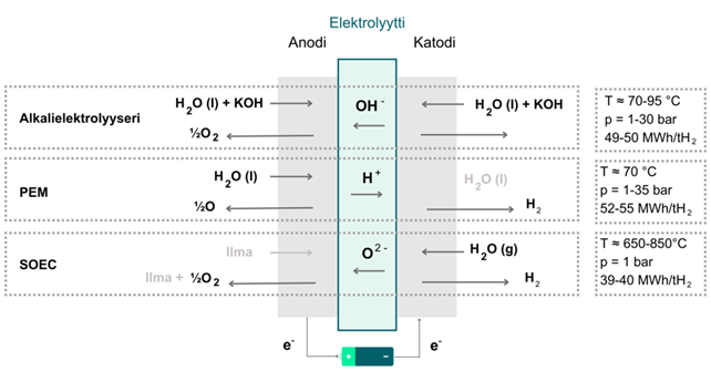
There are different types of electrolysers, and they function differently, e.g. alkali electrolysis, proton exchange membrane electrolysis (PEM) and solid-oxide electrolysis (SOEC) (Figure 1). The most common and longest-running technique is alkali electrolysis.
Figure 1. Electrolytic cell operating principles
Alkaline electrolysis is performed using an alkaline solution, typically potassium hydroxide. Between the metal electrodes is a porous film designed to prevent the mixing of product gases, hydrogen and oxygen. The water molecule is broken down on a cathode into hydrogen and hydroxide ions. The hydroxide ion passes through the membrane to the anode, where two hydroxide ions react, forming oxygen and water. The operating temperature of the alkaline cell is typically 70–95 °C, and the operating pressure is 1–30 bar.
In proton exchange membrane electrolysis, a solid proton-conducting membrane made from special plastic is used as the electrolyte. Similarly to the alkali electrolyser, the membrane separates the resulting product gases from each other. The anode and cathode are pressed against the membrane or integrated into the membrane to form an electrode assembly. On the anode, the water breaks down into oxygen and protons (H+), which move through the membrane to the cathode. On the cathode, the protons react with electrons, forming hydrogen gas. The operating temperature of the PEM cell is typically 50–80 °C, and the operating pressure is 1–35 bar. The hydrogen generated by PEM electrolysis is usually very pure (99.99%) without separate purification.
In a solid-oxide electrolysis cell (SOEC), there is a solid ionic conductive electrolyte between porous electrodes. On the cathode, the water combines with electrons from the external circuit to form hydrogen gas and negatively charged oxygen ions. The oxygen ions pass through a solid ceramic electrolyte membrane and react on the anode to form oxygen gas and electrons for the external circuit. The SOEC cell requires a high operating temperature, typically 650–850 °C. The pressurisation of the SOEC cell is highly challenging, and the operating pressure of the SOEC cell is therefore close to the current atmospheric pressure.
The design and operation of alkali and PEM electrolysers must reliably take into account and prevent excess mixing of the product gases, oxygen and hydrogen, as well as the formation of flammable gas mixtures in the electrolyser equipment or other product gas treatment equipment and gas storage facilities. The amount of mixing of the product gases depends on the design of the electrolyser equipment and may occur, for example, because of an excessive pressure difference over the electrolyser cell separator membrane, damage to the separator membrane as a result of incorrect conditions, or too low a liquid surface in the liquid-gas separators in the electrolyser equipment.
3.2 Steam reforming
In addition to the most commonly used natural gas, the raw materials in steam reforming include methanol, lighter hydrocarbons and other oxygen-rich hydrocarbons. The steam reforming process begins by removing sulphur compounds from natural gas. The reforming process consists of two phases. In the first phase, the hydrocarbon is mixed with steam and fed into a tubular catalytic reactor. The process produces a mixture of hydrogen and carbon monoxide and a lower concentration of carbon dioxide gas. In the second phase, in the water gas shift, carbon monoxide and water vapour react under the catalyst to produce carbon dioxide and more hydrogen. Finally, carbon dioxide and other impurities are separated from the hydrogen produced in the pressure-swing adsorption (PSA) unit.
3.3 Gasification
Gasification is a process in which the combustible material is partially oxidised and heated. The product generated is synthesis gas. Unlike most combustion-based processes, gasification processes work without excess oxygen. This ensures an almost complete conversion of the precursor into synthesis gas. Gasification is used to make hydrogen from coal.
The process begins by mixing a carbon-rich material (biomass, coal) with oxygen, which is heated to 1,800 °C, causing the coal to gasify. The synthesis gas is cooled and purified, leaving only carbon monoxide and carbon dioxide in addition to hydrogen. The purified synthesis gas is transferred to the shift reactor, where it is mixed with steam. In the reaction, carbon monoxide is oxidised into carbon dioxide. After this phase, the synthesis gas contains mainly hydrogen and carbon dioxide, which are separated from each other.
3.4 Partial oxidation
Partial oxidation works like gasification at a lower amount of oxygen than is stoichiometrically required for full combustion. With partial oxidation, hydrogen can be produced from heavy oil, methane or biogas. Pure oxygen is used as the main oxidiser. Partial oxidation can be performed with or without a catalyst.
Partial oxidation without a catalyst occurs at a high temperature, usually between 1,300 and 1,500 degrees, at a pressure of 30–80 bar. The raw material is gasified with oxygen to produce hydrogen, carbon monoxide, carbon dioxide, water and methane. Sulphur compounds are also present in synthesis gas, and soot is generated as a by-product. The temperature can be reduced by using a catalyst. In such a case, the reaction occurs at 700–1,000 degrees.
3.5 Thermochemical water splitting
Thermochemical water splitting is considered a strong candidate for long-term and larger-scale hydrogen production technology. The method is based on repeated series of chemical reactions. These involve intermediate reactions, as well as chemicals that circulate in the process so that the total reactions are balanced. Thermochemical water splitting can occur through thermal energy alone, or another external energy source can be used, in which case it is called hybrid thermochemical water splitting.
3.6 Purification of hydrogen
When hydrogen is used as a fuel, certain quality requirements are set for the hydrogen. International standards (e.g. ISO 14687) include an extensive list of impurities in hydrogen and their maximum permitted concentrations for various applications. In the gaseous hydrogen purification process, water and gases such as oxygen and carbon monoxide are removed from hydrogen gas as impurities. Impurities such as water vapour and carbon monoxide interfere with the operation of the fuel cell, while oxygen and nitrogen reduce the efficiency of the system.
Methods commonly used for hydrogen purification include:
Pressure swing adsorption (PSA) is one of the most commonly used purification methods. A PSA unit contains a tank filled with a specific material. When hydrogen gas flows through the tank, the impurities are adsorbed into the material inside the tank, and the final result is pure hydrogen gas.
Membrane separation typically uses a palladium membrane to purify hydrogen of impurities. Hydrogen penetrates the membrane and flows through it because of a pressure difference. The impurities do not penetrate the membrane, and the purified hydrogen gas is collected on the other side of the membrane.
In electrochemical separation, hydrogen is purified by oxidising the hydrogen atoms on one side of the proton-conducting membrane into protons and reducing the protons passed through the membrane back into hydrogen atoms. This separation process is promoted electrochemically by means of the catalytic properties of membranes coated with palladium or platinum or their mixture. These purifiers are very compact.
In cryogenic distillation, a distillation column is used to separate the impurities from the hydrogen gas based on their boiling points. The purified hydrogen gas is collected at the top of the column, while the impurities remain at the bottom.
4 Hydrogen transmission
For example, the need for storage and transport of the hydrogen produced depends on whether the production takes place in large centralised plants or in lower-capacity local facilities close to the intended application site (e.g. a refuelling station). Hydrogen produced in centralised plants can be transported over long distances and in large volumes. Hydrogen storage capacity is also often needed to balance consumption and production fluctuations. The advantage of locally produced hydrogen is the low transport need.
4.1 Hydrogen transmission pipelines
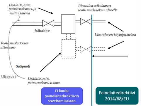
Hydrogen transmission pipelines are pipelines that run outside production plants. In the area of the production plant, the operator of the production plant is responsible for the pipelines, but a building permit must be applied for separately from Tukes (Finnish Safety and Chemicals Agency). A pipeline manager must be appointed to ensure that the transmission pipelines are operated in accordance with the regulations, the building permit conditions and the operating principles drawn up by the operator. Offsite hydrogen transmission pipelines are not covered by the Pressure Equipment Directive (PED).
Transmission pipelines can run on land, on the seabed or in the air on a pipeline bridge, and their pressure can vary from a few bar to dozens of bar. Legislation does not include a specification for hydrogen distribution pipelines, meaning that all offsite pipelines are transmission pipelines.
All offsite hydrogen pipelines are transmission pipelines.
Figure 2. Definitions of onsite and offsite pipelines
Hydrogen transmission pipelines are inspected by a national inspection body approved by Tukes before the pipelines are commissioned and periodically thereafter. The appropriate inspection interval for hydrogen transmission pipelines is 5 years. Tukes may grant the operator a permit to monitor the condition of its pipelines instead of having them inspected by a national inspection body. This requires that the operator’s own inspection system corresponds to the safety level of periodic inspections.
The use of steel grades that are too strong is avoided in hydrogen transmission pipelines because they are more sensitive to hydrogen embrittlement. Experience shows that suitable steel grades include SFS-EN ISO 3183 L360 or API 5L Grade X52 or lower-strength steel grades. These carbon steel grades have relatively low yield strength, which provides resistance to hydrogen embrittlement and other brittle fracture mechanisms.
In hydrogen pipelines, the aim is to minimise the number of seams because seams are the most typical leakage points. Individual pipes are primarily manufactured seamless. However, in some situations, seams need to be used, and individual pipes are connected by welding. In hydrogen transmission pipelines, the joints should primarily be welded (instead of threaded and flange joints) to minimise possible leakage points. In underground pipelines, the joints must be welded. Of the welding seams made during manufacture and installation, 100% are checked volumetrically (RT/UT).
4.2 Hydrogen transfer in containers/trailers/bottles
Gaseous and liquid hydrogen can be transported by lorry, rail and ship. Gaseous hydrogen can be transferred and stored in gaseous form in gas cylinder containers (MEK container) or pipe trailers. The pressure of the tanks is typically 180 to 640 bar. In truck transport, the amount of hydrogen loaded into the trailer depends on the type of tank used. For example, when using gas cylinders, the amount of hydrogen can be between 380 and 900 kg, and the typical amount of hydrogen transported by a pipe trailer is 400 kg. Larger quantities require lighter composite tanks. The transport of liquid hydrogen requires a cryogenic tank. Between 300 and 4,000 kg of liquid hydrogen at a time can be transferred in a tank.
5 Hydrogen storage
The storage of hydrogen is challenging because of its properties. In normal conditions, hydrogen is gaseous and has an energy density of only 3 Wh/l. At normal atmospheric pressure and temperature, 1 kg of hydrogen gas requires a storage volume of 11 m3. Large-scale hydrogen storage therefore requires a high storage density to be profitable. Hydrogen storage forms can be divided into physical and chemical storage.
Physical storage forms include compressed gas, liquefied hydrogen, pressurised liquid hydrogen and slush hydrogen. Slush hydrogen is a combination of liquid hydrogen and solid hydrogen at the triple point (temperature -259.35 °C and pressure 0.0704 bar). Slush hydrogen is mainly used to store fuel for spacecraft, so it is not discussed in more detail in this guide.
The chemical storage forms of hydrogen include various hydrides (metal, complex, chemical and transition metal complexes), adsorption, liquid organic carriers (e.g. benzene/cyclohexane, cycloheptatriene/cycloheptane) and reformed organic fuels (e.g. methane, ammonia). The most suitable form of storage depends on what the hydrogen will be used for – that is, what types of requirements there are for the hydrogen’s transport, purity, storage capacity and storage time and how quickly the hydrogen needs to be used.
5.1 Gaseous hydrogen
Hydrogen is mostly stored as pressurised gas. The typical storage pressure is 200–700 bar. Gaseous hydrogen tanks are pressure equipment and are subject to pressure equipment legislation.
A pressurised hydrogen tank usually consists of three layers. The innermost layer is hydrogen-tight and can be made from metal, compact thermoplastic or a coated composite material. Outside the inner layer is a pressure-resistant layer, which often also serves as a heat insulation layer. The outer shell may be made from metal or carbon fibre.
Hydrogen tanks and bottles are divided into four types:
Type I tanks are fully metallic, usually made from steel or aluminium. A type I tank does not have a separate outer shell, so its manufacture is relatively simple. The simple structure also makes type I tanks relatively inexpensive to manufacture. The maximum pressure of metal tanks is around 200 bar. Type I tanks are heavy and are mainly suitable for industrial or other fixed applications.
Type II tanks are typically aluminium cylinders with strands of glass fibre, aromatic polyamide or carbon fibre around them. The purpose of the strands is to strengthen the wall structure, allowing the inner shell to be made of a thinner layer of metal. This reduces the weight of the tank. The maximum pressures for type II tanks are around 260 bar for the aluminium-glass fibre structure and 300 bar for the steel-carbon fibre structure.
Type III hydrogen tanks are made from a composite material such as glass fibre and aromatic polymer or carbon fibre. The tank has a very thin aluminium or steel coating inside. The pressure resistance of the tank is entirely based on the material of the outer shell. The maximum pressures for type III tanks are around 300 bar for the aluminium-glass fibre structure, around 430 bar for the aluminium-aromatic polymer structure and 700 bar for the steel-carbon fibre structure.
The inner layer of type IV hydrogen tanks is made from a coated composite material. The outer shell is made from a mixture of carbon fibre and thermoplastic. Its inner surface typically has a polymer liner. Type IV tanks are around 70% lighter than type I tanks. Type IV tanks are used especially in mobile and aeronautical applications where low tank weight is particularly important. Manufacturing type IV tanks is much more expensive than other types of tanks.
Tanks may be stored above ground or underground. Unprotected above-ground tanks are exposed to weather phenomena and physical damage and require space. In the weather protection of hydrogen tanks, attention should be paid to the fact that in the event of leakage, hydrogen must not accumulate under the cover. Ground-covered tanks are difficult to inspect and subject to corrosion, and it is also difficult to detect leaks from ground-covered tanks.
5.2 Liquid hydrogen
Liquid hydrogen is used in space technology and especially in the storage of large amounts of hydrogen. Liquid hydrogen is also used in some mobile and aeronautical applications.
The advantages of liquid hydrogen storage include space saving, high hydrogen purity and the possibility of low-pressure storage. Liquid hydrogen is typically stored at a pressure of less than 5 bar. The drawbacks of liquid hydrogen storage include high energy consumption, hydrogen emissions to the atmosphere caused by liquid hydrogen evaporation (boil-off) and special requirements for the tank material. Hydrogen liquefaction requires complex equipment, including compression, cooling and gas recycling.
A liquid hydrogen storage tank and the related equipment (pipes, valves, etc.) must withstand a large temperature difference (liquid hydrogen -253 °C; the environment may be +30 °C) and heat expansion and contraction because of temperature differences. The low temperature of liquid hydrogen makes many materials fragile and, because of its small size, the hydrogen molecule easily penetrates many materials. In addition, ice formation should be avoided as it increases the embrittlement of materials. Liquid hydrogen does not cause corrosion.
A significant challenge and risk factor in the storage of liquid hydrogen is the boil-off phenomenon – that is, the vaporisation of liquid hydrogen. Vaporisation causes two types of losses to the system: the energy used to liquefy hydrogen is wasted, and the vaporised hydrogen enters the atmosphere through a vapour duct. Vaporisation can occur through a variety of mechanisms, and its amount is directly correlated with the size, shape and insulation of the tank and with hydrogen-specific isomer forms. The vaporisation phenomenon can be caused by the intervariability of hydrogen isomers, heat transfer from the environment, heat increase because of hydrogen splashing inside the tank and pressure difference caused by liquid and gaseous hydrogen deposition. A difference in pressure may also occur when cold liquid hydrogen is filled into a tank, allowing the saturation pressure to rise above the maximum operating pressure of the tank. Vaporisation cannot be completely prevented, but with an efficient tank solution, vaporisation can be limited to 0.1% per day. Because of vaporisation, the filling volume of a liquid hydrogen transport tank must not exceed 85% of the maximum volume in road transport. When storing liquid hydrogen, the possibility of boiling liquid expanding vapour explosion (BLEVE) must also be considered.
Liquid hydrogen is stored in a vacuum-insulated double-jacketed tank. In addition to the vacuum, multi-layer insulation such as glass fibre, aluminium membranes and polymer plates are installed between the inner and outer tanks. The inner tank is usually made from austenitic stainless steel, and the outer tank is usually made from ferritic steel.
Because of the vaporisation phenomenon, the tank must be equipped with a safety valve and a vaporisation system. Dents in the tank wall can cause the vacuum to disappear and thus the temperature and pressure to rise in the tank. A liquid hydrogen tank should therefore be equipped with collision barriers. The formation of ice in the tank equipment (e.g. valves) should also be avoided, as it can cause equipment malfunction.
In the case of liquid hydrogen loading and tank filling, the pipes must be cleaned with an inert gas (helium or nitrogen) to prevent a flammable air-hydrogen mixture. The ignition range of hydrogen at 1 bar and 25 °C is between 4 and 75 vol%. The minimum ignition energy of hydrogen is very low compared with other fuels (0.017 mJ), and hydrogen has low electrical conductivity, which can lead to the generation of static electricity and a fire-causing spark in pipe flows, for example. For these reasons, the insulation of ignition sources and grounding are important at hydrogen handling sites.
The problem with liquid hydrogen equipment is the condensation of oxygen and air on surfaces. When storing liquid hydrogen, attention must also be paid to the fact that in phase transition from liquid hydrogen to gaseous hydrogen, the volume of hydrogen increases around 800 times.
5.3 Pressurised liquid hydrogen
Pressurised liquid hydrogen is stored at a pressure higher than the critical point of hydrogen. The advantage of pressurised liquid hydrogen is its high storage density (= less space required), and that there is no phase transition (vaporisation) during storage and the pressure increase is slower than with liquefied hydrogen. In addition, there are less vaporisation losses than with liquefied hydrogen. The disadvantages of pressurised liquid hydrogen storage include high energy demand (compression and cooling), challenges for the storage material (cold and pressure resistance), and the fact that changes in ambient temperature can lead to vaporisation more easily than with liquid hydrogen. In such a case, hydrogen escapes from storage through the pressure-reducing valve.
5.4 Hydrides
Hydrogen can be stored as metal, complex, transition metal and chemical hydrides. Hydrides have the advantage of a relatively low temperature range, storage safety and stability. The drawbacks include storage capacity, limited reversibility between hydride formation and decomposition, and heat management. Hydrides require heat to extract the hydrogen. In addition, hydrides have thermodynamic and kinetic constraints on hydrogen storage and release, and flammable by-products may be formed in hydrogenation reactions.
5.5 Other hydrogen carriers
In addition to the above, hydrogen can be stored in organic hydrogen carriers, adsorbed or in reformed fuels.
Organic hydrogen carriers are liquids that can store hydrogen reversibly. Examples of such liquids include benzene/cyclohexane and cycloheptatriene/cycloheptane. In liquid organic hydrogen carriers, hydrogen storage takes place at room temperature and pressure, whereas binding and extracting hydrogen require a temperature of 200–350 °C. The downsides of organic hydrogen carriers are low hydrogen storage density, high energy demand for hydrogen release and the need for carrier purification.
The adsorbed hydrogen is stored by physically binding it to a material with a large surface area. Reformed fuels include methanol and ammonia, for example. The problem with these is that they often require a carbon source. Ammonia is considered to be a promising hydrogen carrier, but its challenges include high energy demand during synthesis, ammonia toxicity and nitrogen oxides generated during combustion.
Organic liquids and reformed fuels are discussed in the Tukes guide on the storage of hazardous chemicals (in Finnish), so they are not discussed in more detail in this guide.
6 Filling of hydrogen bottles and containers
Hydrogen transport containers, bottle sets and individual bottles are usually filled using a compressor. With the compressor, the hydrogen pressure is increased to a suitable pressure level depending on the purpose and type of bottle.
Hydrogen bottling equipment is sold by several manufacturers. The filling unit for individual bottles may be a manual filling point for one bottle or a fully automatic filling carousel.
Special filling heads are used to fill bottles and bottle sets. Filling heads can be attached to bottles and bottle sets, and valves can be operated manually or by automation.
Another option for filling hydrogen bottles is a cascade fill, where smaller bottles (e.g. 10 l) are filled from larger ones (e.g. 100 l) without a compressor. Large bottles can be filled on-site with a compressor or replaceable bottles can be used. In cascade filling, the high-pressure gas flows into an empty bottle with lower pressure until there is no difference in pressure between the two bottles.
Because hydrogen is a light gas, small leaks are easily be accumulated in a closed space at the ceiling. For this reason, ventilation of the filling site of the hydrogen bottles must be ensured, and recesses in the ceiling should be avoided. In addition, hydrogen handling facilities must be equipped with hydrogen detectors.
7 Hydrogen distribution stations
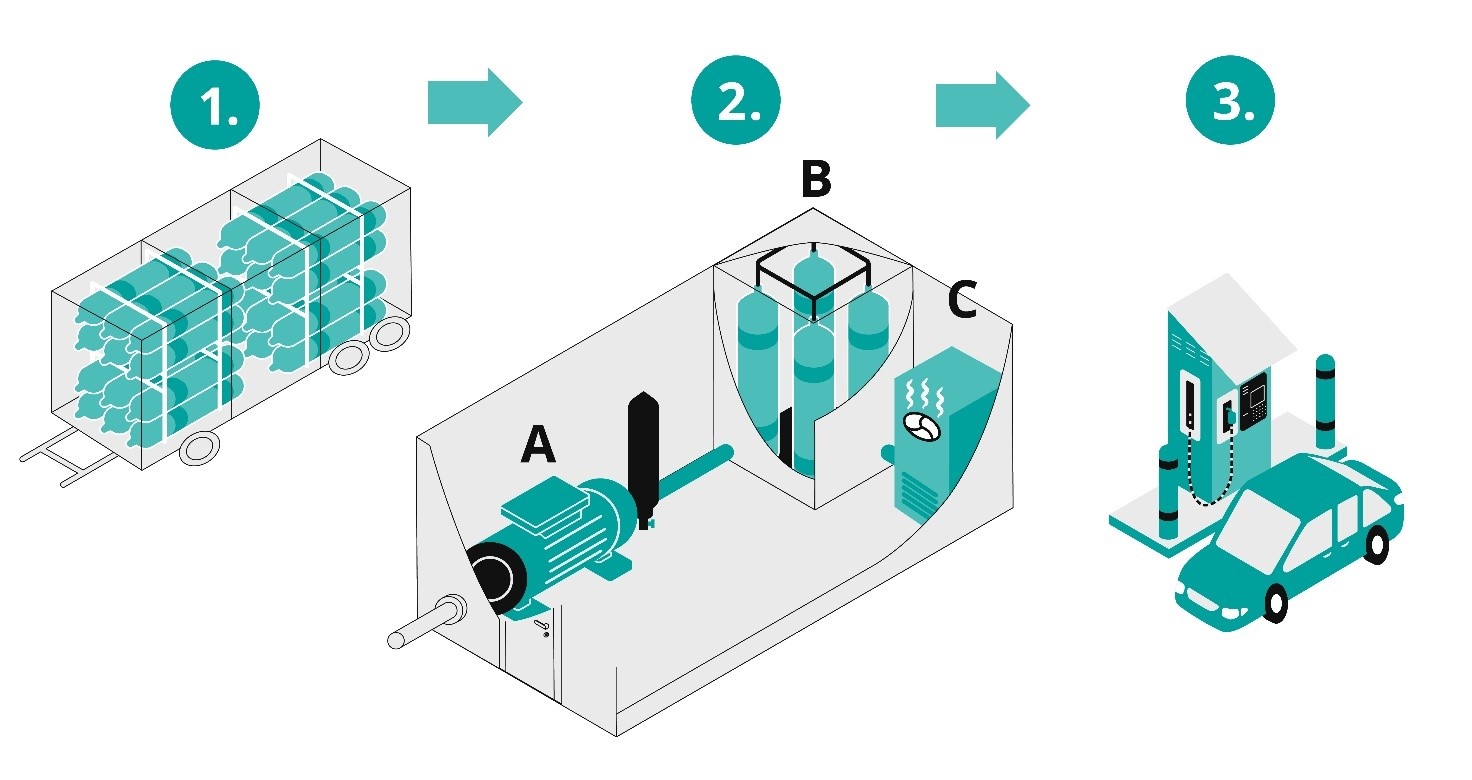
The refuelling of a hydrogen-powered vehicle with gaseous hydrogen is based on the pressure difference. In the buffer tanks of the refuelling station, the hydrogen is stored at high pressure, and during refuelling, the hydrogen is transferred to the hydrogen tank of the vehicle, where the pressure level is lower. At a hydrogen refuelling station (Figures 3 and 4), the main components are hydrogen storage tanks, a compressor, high-pressure storage, a pre-cooling system and a hydrogen refuelling point.
Figure 3. Refuelling station: storage tanks (1), compressor (2A), high-pressure storage (2B), pre-cooling system (2C), hydrogen refuelling point (3)
A pre-cooling system is required because the hydrogen temperature increases when refuelling high-pressure hydrogen. Without cooling, the temperature in the vehicle’s hydrogen tank may become too high, which can damage the tank and cause leaks. In the case of rapid refuelling, there must be an automation connection between the vehicle and the refuelling station, which limits the refuelling speed of the distribution station if the temperature in the vehicle’s storage tank rises too much, for example.
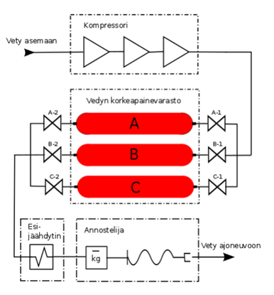
Figure 4. Hydrogen refuelling station
In addition to these, the refuelling station has equipment for transferring hydrogen, ensuring its purity and controlling dosage. Components and systems related to measurements (temperature, pressure, flow) and controls are also essential for the operation of the station and for successful refuelling. To ensure safety, the station has safety automation and protection systems. Essential safety functions and equipment at distribution stations include insulation valves between hydrogen storage, buffer tanks, compressors and distribution meters, which are closed by safety automation to limit the consequences of accidents in the event of leaks.
The refuelling event and the change of storage container are the most critical factors in the safety of a distribution station and the most likely causes of leaks. At distribution stations, the risk is increased by consumer activity. Accidents can occur at gas distribution stations if the driver forgets to detach the refuelling hose after refuelling. This is prevented by means of infrared communication between the car and the refuelling station, in which case the car does not start or move when refuelling is still in progress. How this precaution works in practice depends on the type of vehicle.
It is also essential to ensure the condition of the gas hoses by checking them regularly and frequently enough. The gas hoses in the distribution meter must be of an appropriate length and design (suitable for hydrogen, the pressure used and a temperature of down to -40 °C). The automation of the distribution station must ensure the tightness of the refuelling hose before the actual refuelling begins.
A hydrogen refuelling station must be equipped with a temperature-compensated filling system designed to ensure that the pressure in the gas tanks of gas vehicles does not exceed the permissible pressure under any circumstances.
Stationary storage facilities for pressurised gas (buffer storage) must be manufactured and inspected in accordance with the pressure equipment regulations with a CE marking. The equipment for measuring the amount of hydrogen refuelled at a hydrogen distribution station must be type-approved and verified before being put into service. The verification is carried out by an approved inspection body.
The canopy of the distribution station is designed so that recesses and other structures where leaked hydrogen can accumulate are avoided. Gas detectors are installed in enclosed spaces (e.g. compressor containers), which trigger an automatic safety function such as closing the valves and starting emergency ventilation.
8 Location of hydrogen production facilities, storage facilities and distribution stations
The locations of hydrogen handling sites are planned in order to avoid and minimise the impacts of a possible accident on other operations in the vicinity of the site. Risk assessment is used to identify accidents with the most significant consequences, the impact range of which is assessed by means of a consequence analysis. In addition to the impact analysis, accident probabilities are assessed. According to chemical safety legislation, unlikely accidents do not need to be taken into account when determining protective distances for the location of a production plant. However, in such a case, the operator must be able to demonstrate that the accident in question is sufficiently unlikely to be disregarded when assessing the safety of the location.
Unlikely accidents do not need to be taken into account when determining protective distances for the location of a production plant. However, an assessment of the consequences of unlikely accidents must be carried out for the operator’s own and for the rescue services’ preparedness planning.
In the location of hydrogen production plants and distribution stations in relation to external sites, special attention is paid to sensitive sites such as care facilities, schools, kindergartens, business centres, etc. The criteria for the pressure, heat and health impacts of the locations of production plants and distribution stations are presented in the Tukes guide on the location of production plants. The locations of operations within a plant or distribution station area are assessed in accordance with the same principles. Instructions on the location of operations can be found in Standard SFS 3353:2019 (“Combustible Chemicals Production Plant”).
The consequences of a hydrogen accident are assessed by modelling different leakage and ignition scenarios. The amount of data and the modelling methods for assessing the consequences of hydrogen accidents are not as advanced as those for hydrocarbon accidents. For this reason, it is necessary to use a conservative perspective in the selection of input data and in the assumptions of the scenarios.
The modelling methods can be roughly divided into analytical and computational fluid dynamics (CFD) methods. Analytical methods use fewer variables than CFD to obtain the modelling result and therefore provide rougher answers.
However, the results obtained by analytical methods may be sufficient to assess the impacts further from the leakage or ignition point. More accurate results can be obtained with CFD modelling, which takes into account environmental geometry and uses the properties of chemicals and calculations based on them. Near the ignition point, the most reliable modelling is obtained using CFD modelling, which can best be used to estimate the location of operations on the production plant site.
The analytical modelling method is suitable for the planning of the entire plant location, as its accuracy is sufficient for estimating the consequences of accidents extending beyond the site. When carrying out modelling, it must be ensured that the programme and calculation method concerned are suitable for hydrogen accident modelling, and that the modeller has sufficient knowledge for hydrogen modelling.
8.1 Accidents to be taken into account when placing production plants
The most important factors to consider in the location of a hydrogen production plant are the hydrogen pressure and storage volume and the resulting accident risks. Potential hydrogen leakages are identified as accident scenarios. When planning the location of the plant, the impacts of accidents at industrial plants on adjacent sites (e.g. thermal radiation from fire) on the hydrogen production plant are also taken into account.
To ensure a safe location, the operator assesses the consequences of the accident scenarios identified by the operator through consequence analysis (modelling). The results of the modelling include the extent of the flammable gas cloud formed as a result of hydrogen leakage, the thermal radiation impact of a fire and the pressure impacts of an explosion. The results of the consequence analysis include:
The length of the jet flame and its thermal radiation impact
The size of the hydrogen cloud with a flammable concentration
The thermal radiation and pressure impacts of the explosion (VCE or jet explosion)
The results of the modelling are significantly affected by the data used, so these should also be presented in the modelling reports. The results of the modelling should show at least the following input data:
Leak hole size
Pipe diameter
Process conditions (pressure, temperature, etc.)
The mass of hydrogen in a flammable gas cloud
Leak time
Leak height
Obstacle density
The weather types used in the calculation
If a pipe break is not considered possible, the grounds for this must be presented.
A hydrogen pipe break is modelled, but the results do not need to be taken into account in terms of the location of the hydrogen plant if the operator can demonstrate that a pipe break is highly unlikely. When assessing the likelihood of a pipe break, consideration is given to, among other aspects, the number of hydrogen pipes and their connections, the layout of the pipelines and the risks to the pipelines arising from other operations of the plant or refuelling station.
An accident scenario is also selected for modelling where the leak hole size of the hydrogen pipe is 10% of the cross-sectional area of the pipe. A hole in a pipe is more likely than a complete pipe break. The selected size of the hole is 10% of the cross-sectional area of the pipe in accordance with international practice. The leak time depends on the safety arrangements used, and the reliability of these must be credibly justified.
To assess the consequences of an accident, leakage from the pipe with the highest cross-sectional area and from the pipe with the highest pressure is modelled. In terms of the location, the scenario with the greater impact area is taken into account.
If hydrogen bottle containers are filled at the production plant, the accident scenarios also include a break in, or detachment of, the hose used to fill the hydrogen bottle container. The consequence analysis takes account of the response time of the leak-stopping system.
The hydrogen plant or distribution station must not be placed under overhead lines. In addition, the lateral distance to overhead lines is estimated based on the consequences of a possible accident. This protects electricity transmission and, on the other hand, prevents the ignition of leaked hydrogen as a result of sparking from overhead lines.
Hydrogen-producing electrolysers are also planned to be installed on offshore platforms at the base of wind turbines. In this case, the hydrogen is transferred through an underwater pipeline to the mainland. In such a distributed location model, the amount of hydrogen on the production site is very small.
8.1.1 Accidents to be taken into account in terms of the location of a distribution station
The location of a hydrogen distribution station takes account of the same aspects as the location of a hydrogen production plant.
In addition, the following aspects are taken into account in terms of the location of a distribution station:
Location in relation to the customer buildings of the distribution station (service station store or café, car wash, car maintenance shop, etc.)
The relative location of the equipment in the distribution station area
A relatively low explosion pressure (0.05 bar) can cause damage to buildings, and the failure of roof structures is particularly dangerous. This may pose a risk to the customers and staff of large shop and café buildings at service stations.
In addition to the accident scenarios concerning the production plant, the detachment of the refuelling hose and the thermal radiation caused by the combustion of the vehicle are modelled as an accident scenario for the distribution station.
For the scenario concerning the full detachment of the hose, the input data includes:
Pressure used at the station
Hose size
The response time of the protection function (response time of the safety function to stop the leakage, from the start of the leak to the end of the leak)
8.1.2 Location of hydrogen equipment and functions in the production plant and distribution station area
In addition to hydrogen production or refuelling, there are almost always other operations in the production plant and distribution station area. When determining their locations in relation to one another, the same principles as for the location of the entire plant are generally followed, and the same scenarios are used as the input data for the modelling. Persons working on the production plant site have been familiarised with the dangers arising from the operation. Therefore, a slightly higher risk may be accepted for operations within the plant than if the consequences of the accident affected operations or persons outside the plant.
Operations and their locations are designed so that accidents can be prevented from spreading between structures or operations, and that the impacts of accidents can be kept to a minimum. In such a case, account must be taken of the risks to other operations caused by hydrogen storage and use, as well as the risks to hydrogen storage caused by other operations such as liquid fuel refuelling or electric car charging. Special challenges are posed by multi-fuel distribution stations. These must take into account both the distribution points of different fuels and the charging points for electric vehicles, as well as the service station/café building.
The impacts of accidents are assessed by modelling heat and pressure impacts. There may be limited space in the plant or distribution station area, in which case there may be a need to limit heat and pressure impacts by means of a protective wall, for example. However, other impacts of the wall must also be taken into account, such as the reflection and intensification of the pressure wave, the accumulation of hydrogen behind the wall or the increase in the turbulence of the air flows caused by the wall.
The location of the operations must also take into account the location of the air inlets in different buildings. The potential sources of hydrogen leakage are placed sufficiently far away from the above inlets to prevent hydrogen from entering another building through the air inlets.
In terms of the locations of hydrogen structures, it must also be ensured that no trees, electric posts or other tall structures can fall on them, nor can outdoor lamps or similar loose pieces fall on them. The locations selected for hydrogen tanks or equipment reduce the possibility of vehicles colliding with them, by means of collision barriers, for example. In addition, the placement of equipment or tanks in road curves, at a hill or other places that increase the risk of collision is avoided.
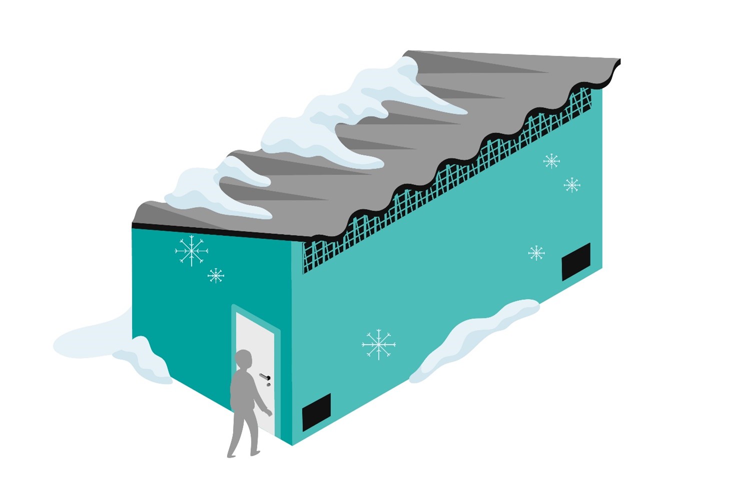
An internal explosion in a compressor space or bottle storage placed in a container causes a pressure wave and pieces flying off broken structures. The lightening of structures or the direction of discharge of explosion protection hatches is designed so that the pressure wave and loose pieces are directed in a safe direction. If the lightened structure is the roof of the container, the roof should be sloped (lean-to roof) to prevent snow and ice from accumulating on the roof and to direct the hydrogen leakage out through the highest point of the roof. To this end, a vent with a grill is added under the eaves of the roof (Figure 5).
Figure 5. A building for hydrogen handling and storage
Unauthorised access to the hydrogen storage site and compressor container must be prevented. They must be equipped with a lockable enclosure with a motion or touch sensor, and with camera surveillance at unmanned refuelling stations. Hydrogen equipment and pipes must be equipped with collision barriers. To prevent external impacts, hydrogen pipes from bottle storage to the refuelling point are installed underground.
In addition to chemical safety legislation, the location of functions in relation to one another is regulated in electrical safety and building legislation, for example. Instructions on the location of operations can be found in Standard SFS 3353:2019 (“Combustible Chemicals Production Plant”).
8.2 Impact of land use planning on location
In terms of the location of a hydrogen production plant, the suitability of the intended site is assessed in the same manner as that of any other chemical plant. When considering a location, it must be ensured that the current land use plan for the plot in question allows for the placement of the chemical plant. Tukes recommends a “T/kem” marking for plots where a large-scale chemical plant is planned to be placed, but other land use markings are also possible. Other suitable land use plan markings for a hydrogen plant include “T” (industrial and storage area), “TT” (site for industrial operations with significant environmental impacts) and “EN” (energy supply area).
Other land use plans are also possible if:
The planning regulations make it possible
The municipality is in favour of a plant on the site
The planned use of the surrounding plots will not be compromised
The consequences of accidents are limited to the site
In addition to the site of the hydrogen plant, the planning markings of the surrounding plots must be taken into account. The hydrogen plant to be built must not limit the use indicated in the land use plan for the surrounding plots. In addition to the land use plan, the accident hazards caused by the plant are always assessed, so only the suitability of the plan for a hydrogen plant does not ensure its placement on the intended site.
For minor sites, the land use plan marking may vary. For example, a marking for another type of distribution station may be suitable for a hydrogen distribution station. However, not all plots planned for distribution station operations are suitable for a hydrogen distribution station in a densely built urban environment, for example. Distribution station operations must not conflict with the land use planning regulations and must not restrict the planned use of the surrounding plots.
For more information about the location of chemical plants and taking account of the risks of accidents, see the Tukes guide on the location of production plants (in Finnish).
8.3 Location plan for pressurised hydrogen equipment
Hydrogen equipment and tanks are pressure equipment, the safety of which is assessed by an inspection body and, in some cases, also by Tukes in connection with the processing of the chemical safety permit. The actual location plan for the pressure equipment is inspected by an inspection body. For example, a location plan is required for pressure equipment that is placed on its operation site indoors, in public spaces or in the immediate vicinity of a public access route, and that is
pressure equipment for which the product of the numerical values of the maximum permitted operating pressure and volume exceeds 10,000 bar x litre, or
transportable pressure equipment or a combination of gas bottles with a capacity of more than 450 litres, or
hydrogen-containing pipelines larger than DN 50.
A separate location plan is not required if Tukes has checked the safety of the pressure equipment location in a permit procedure under the Act on the Safe Handling and Storage of Dangerous Chemicals and Explosives. Even if a plant has a chemical safety permit granted by Tukes, the plant may have pressure equipment that requires a location plan if Tukes has not approved the location of all pressure equipment in its permit decision. A location plan is required for pressure equipment at distribution stations that is subject to a permit issued by the rescue department.
9 Aspects to consider in planning hydrogen handling
9.1 Materials
Hydrogen equipment typically contains a wide range of structural materials – metallic and non-metallic materials and composites. The suitability of all materials for the operating conditions and their durability in the event of an accident must be carefully assessed. Material choices must be based, where possible, on standardised solutions whose safety has been proved in practice.
Hydrogen poses special requirements for the structural materials of equipment and pipelines. In material choices, particular consideration must be given to hydrogen pressure, the design temperature, possible other contents and contaminants, and the type of load.
Temperature is an important factor in assessing the suitability of materials for hydrogen use. In liquid hydrogen applications, the boundary conditions for materials set by cryogenic conditions, such as brittle fracture tendencies (material transition temperature) and stresses caused by high temperature differences in the components, must be taken into consideration.
The use of hydrogen also causes stress on the materials. Hydrogen is pressurised in a buffer tank just before use. The pressure fluctuations are large, and their impacts on the material must be taken into account.
Hydrogen poses challenges to material choices mainly in two ways:
Penetration through the material, causing direct leakage
Reaction with the material, causing changes in the properties of the material and thus deterioration of the structure
Hydrogen production and storage facilities are made from non-combustible materials. If the purpose of the structures is to protect hydrogen equipment from an external fire, for example, or to reduce the protective distance to external objects, the durability of the structures in a fire must be determined in accordance with this objective.
9.1.1 Metallic materials
As a small molecular gas, hydrogen is able to penetrate inside metal at high pressures. The suitability of steels for hydrogen use is affected by a number of factors such as chemical composition, heat treatment, mechanical treatment, microstructure, impurities, residual stresses and strength. Hydrogen penetrated into the material in high-strength carbon steels, nickel alloys, titanium and certain stainless steels (e.g. 17-7PH, UNS S17700) causes a significant decrease in toughness (hydrogen embrittlement).
Hydrogen embrittlement is a phenomenon that lowers the elongation at break and impact strength of the material without significantly affecting the strength properties of the material. Embrittled material can break suddenly as a result of overload. Hydrogen also significantly reduces the fatigue life of steels because the hydrogen penetrated into the material accelerates the crack growth rate. The reduction in fatigue strength must be taken into account, when necessary, in addition to material selection, in other design details affecting fatigue life.
Certain impurities, especially hydrogen sulphide, can cause atomic hydrogen penetration into the material as a result of the corrosion of carbon steels. Hydrogen accumulates in microscopic discontinuities in the material and causes cracks.
At high temperatures (around 200 °C ->), the hydrogen penetrating into carbon steel can react with carbon in the steel to form methane. In such a case, the microstructure of the steel is depleted of carbon. As a result, microscopic cracks are created in the structure. and the strength of the steel is significantly reduced.
Austenitic stainless steels are generally thought to be more resistant in hydrogen use without embrittlement. Acid-resistant steels (e.g. AISI 316/316L, EN 1.4404) have a lower hydrogen embrittlement tendency than stainless steels (e.g. AISI 304/304L, EN 1.4307). In the case of stainless steel, care must also be taken when selecting the material, and the impacts of different manufacturing techniques such as welding and cold forming on the microstructure of the steel and thus on hydrogen resistance must also be taken into account.
9.1.2 Other materials
Composite materials have been used as a structural material for pressure tanks used specifically for hydrogen. A specification of tank type is presented in section 5.1 of the guideline. Further information about such tanks is available in international standards.
When plastic materials are used, it must be ensured that the chosen plastic material conducts electricity so that it can be grounded. Attention must also be paid to the fact that the resistance of plastic to fire, temperature and UV light is often lower than that of metal. However, there are some plastic applications for hydrogen, such as type IV fuel tanks for hydrogen vehicles, which are made from a plastic-coated polymer-reinforced material. Some electrolysers use plastic composite piping and coatings in part of the process. For plastic to be used, it must be possible to demonstrate its suitability for hydrogen use and conditions of use in a credible manner.
There are experiences of various rubber and polymer seals in hydrogen use. Hydrogen penetrates these materials much more easily than metal materials, which must be taken into account in the design. At high pressures, special attention should be paid to the selection of organic sealing materials, since hydrogen penetrated into these materials can cause mechanical damage to the seal as a result of a rapid pressure reduction.
9.2 General planning guidelines
The aim of planning is to prevent the occurrence of a hydrogen accident and to reduce the consequences of a potential accident. Natural safety can be promoted by reducing a potential hydrogen leakage by making hydrogen pipes as small as possible and installing systems to reduce flow in tanks and pipelines. Protective plates may be installed at identified potential leak points to guide the leak or fire in a safe direction. A sufficient distance between the pieces of equipment ensures that the pressure of, or loose pieces from, a hydrogen explosion do not damage other equipment.
Because of the possibility of hydrogen explosions in enclosed spaces, the facilities are either designed to withstand an explosion or equipped with a lightened structure or explosion hatches, through which the explosion pressure can be released in a safe direction. Safety valves are used to prevent the pressure rise of the equipment above the rated operating pressure, the discharge point of which must be safe and classified appropriately. The safe position of shut-off valves in the event of loss of electricity or compressed air is determined on the basis of a risk assessment and ensured by means of a spring function, for example.
Hydrogen is a lighter gas than air, so ventilation holes in hydrogen handling rooms are placed at the highest points of the space. The design should avoid places where hydrogen gas can accumulate. These include recesses in the ceiling and spacing between the beams, for example. A dense pipeline system can also form a place where hydrogen gas can accumulate. In a hydrogen container, the danger posed by vents must also be taken into account: the flames of an explosion may burst out of the vents (Figure 6).
Figure 6. The flames of an explosion burst out of the vents in a safe direction
The hydrogen equipment is designed so that it is possible to inert it in connection with maintenance, for example. It must be ensured that oxygen levels are below the limit value in all situations. In practice, this requires ensuring sufficient reliability through safety automation, for example.
The hydrogen facility classification typically takes into account minor intentional (ventilation) and unintentional leaks. In these, the leaked amounts and thus the potentially explosive area they form are small.
Hydrogen has a high self-ignition temperature (560 °C). This characteristic temperature is used to determine the maximum surface temperature for equipment used in hydrogen-exposed environments, including failure situations.
An important safety device for the storage of gaseous hydrogen is a safety valve through which hydrogen can be removed from the tank when the pressure rises, the tank heats up, or both occur simultaneously. Pressure-responsive valves or valves that open at a certain temperature may be used as safety valves. Depending on the type of valve, the valve closes when the pressure level or temperature returns to normal or remains open. However, a sudden discharge of high-pressure hydrogen along the discharge pipe can lead to hydrogen self-ignition in the pipe when the hydrogen pulse pushes air ahead of it. This risk must be taken into account in planning.
Temperature-activated safety valves open when the temperature reaches 108–110 °C. Temperature-activated safety valves are used to prevent dangerous tearing of the tank walls typically caused by overheating of the composite tank. A safety valve that is activated at a certain temperature does not close automatically, but is designed to release hydrogen from the tank in a controlled manner.
Hydrogen pipelines running on site are designed, manufactured and installed in accordance with the requirements of the Pressure Equipment Directive (PED). Since hydrogen is a chemical classified as hazardous, all hydrogen pipelines must be manufactured at least in accordance with the requirements of level 1. At distribution stations in particular, hydrogen pipelines are located underground, where possible, to reduce the risk of damage. In underground pipes, a double-jacketed structure and only welding joints are used.
The aim of flaring is to burn gas in a controlled manner. This prevents the risk of explosion. Flaring is used, for example, in the discharge of gas pipelines and in the removal of excess hydrogen gas from the process. The main components of the flaring system are the burner, support structure, pipelines and auxiliary equipment. Auxiliary equipment includes an igniter and a flame guard, for example.
As a small molecular substance, hydrogen penetrates materials easily and leaks even from small gaps. For this reason, potential leakage points, such as flange joints, should be avoided in the design. When designing the pipelines, it is also important to take into account that at high pressures, the leak hole size is an essential factor affecting the magnitude of the hydrogen leakage. The pipe size should be designed to be as small as possible.
Pressed joints are permanent joints, but because of the difficulty of ensuring tightness by checking and of verifying the method in accordance with the PED, they are not recommended for use in hydrogen pipes. Compression joints (e.g. shear ring-type joints) may be used as openable joints.
At the production plant, hydrogen is transferred through a hose from the tank to the bottle container or tube trailer, in which it is transported to a distribution station, for example. The plant must have a system which will cut off the hydrogen supply from both the bottle container and the tank in the event of hose leakage. Similarly, the distribution station must be equipped with a system to stop hydrogen leakage.
The hydrogen quality must be such that the equipment and pipelines can withstand it, and on the other hand, the equipment must be designed to withstand the hydrogen used in them. In the design of hydrogen tanks, particular attention must be paid to the impacts of potential cyclic loading.
Hydrogen plants and distribution stations are also monitored remotely, in which case the control of the plant takes place in a control room located elsewhere. Hydrogen plants, and especially unmanned stations, must take into account security threats, such as cybersecurity and regional security. More information about this topic can be found in the Tukes guide on preparing for security threats in the handling and storage of hazardous chemicals (in Finnish).
9.3 Detection and management of leaks
All hydrogen equipment is primarily placed in outdoor facilities in well-ventilated conditions and implemented with as loose a placement design as possible, avoiding cramped process facilities. However, this is not always possible, and the impacts of the enclosed space must be taken into account.
In indoor facilities, the hydrogen concentration can be reduced by sufficiently effective ventilation that can be programmed to increase effectiveness at a specific hydrogen concentration. However, ventilation is only useful in relatively small hydrogen leaks. Because of the wide flammability range of hydrogen (4–75%) and high pressure, ventilation in larger leakages cannot be arranged to be sufficiently high to reduce the hydrogen concentration to a non-explosive level, meaning that more effective ventilation can only be relevant in terms of mitigating the consequences of hydrogen leakage.
The timely detection of hydrogen embrittlement sets specific requirements for predictive maintenance. Cracking is practically impossible to detect with the naked eye, so material choices and NDT methods in the inspection of hydrogen equipment play an important role. NDT testing can be divided into volumetric (material penetration) and surface testing methods. Volumetric methods include X-ray and ultrasound, which are used to detect defects in welds and to measure the thickness of the wall of the pipe, for example. Surface testing methods include, for example, the intrusion liquid or magnetic powder method, in which a dyed liquid or magnetic powder accumulates in a crack or corrosion point and makes it visible at magnification.
Hydrogen leaks can be difficult to detect organoleptically, as the leaks are often small and the hydrogen is colourless and odourless and burns with an invisible flame in daylight. In some cases, high-pressure hydrogen leakage can be heard as a strong buzzing sound. However, the detection of a leak is essential to enable the necessary measures to be taken.
Various technical aids are used to detect hydrogen leaks, such as gas detectors, pressure sensors, ultrasonic detectors, mass spectrometers and colour-changing leak tape. Gas detectors must be placed so that they can detect the gas released in the event of a leakage. In practice, detectors are placed close to possible leakage points and at the highest points of the facility. The optimal placement of detectors should be ensured by modelling the movement and accumulation of hydrogen leaks from the equipment in the space.
Gas detectors control alarms, warning lights and sound alarms and, if necessary, the stopping and isolation of the equipment by means of safety automation to limit the duration and number of leaks. Especially at distribution stations, alarms must be clear and identifiable to customers. The gas detector can also be combined with ventilation measures, such as the efficiency of the ventilation of the compressor space.
The detection of leaks in underground pipes is ensured by using a double-jacketed pipe solution. In such pipes, the space between the pipes may be pressurised or open. If the outer pipe is open at its end, the intermediate space is ventilated. and the outlets are equipped with hydrogen sensors.
The ignition energy of hydrogen is at its lowest (0.017 mJ) when the hydrogen concentration in the air is 30%. In such a case, the burning rate of hydrogen is also highest. Hydrogen burns with a bright flame that is difficult to detect and does not form smoke. The heat radiation intensity of the flame is low, meaning that it does not emit heat into the environment in the same way as a fire or natural gas flame. This makes it difficult to detect a hydrogen flame. The detection of a hydrogen flame can be made easier, for example, by means of thermal cameras or a flame detector designed to detect hydrogen flames.
In the event of a hydrogen leak, the most important aspect is to detect the leak quickly and to stop it. This may require an automatic system that stops all or part of the equipment depending on the location or number of leaks.
A hydrogen leak is easily ignited even if it is a controlled leakage, meaning that the design of the safety valve must always assume that ignition is possible. This must be taken into account in the direction of discharge of safety valves and in the determination of adequate protective distances around the discharge points. The discharge direction should preferably be upwards, not towards buildings or areas where people may move. The hydrogen pipelines and equipment are rinsed with an inert gas (e.g. nitrogen) to remove oxygen before hydrogen filling and after hydrogen discharge and, if necessary, after the release of the safety valve. In other words, nitrogen gas, for example, must be available for the maintenance of hydrogen equipment.
10 The hazards of hydrogen and the consequences of hydrogen leaks
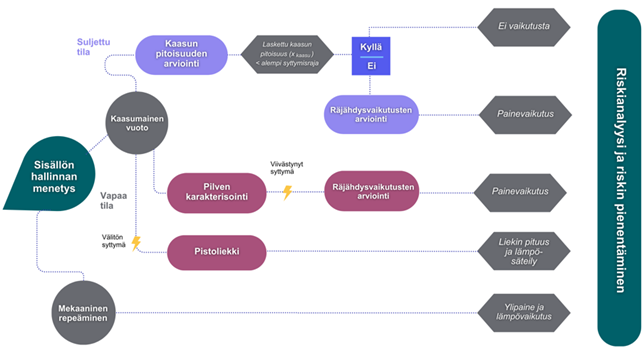
Accidents caused by hydrogen are fires and explosions. The intensity and consequences of these depend on the amount of hydrogen leaked, the process conditions and the ignition point, and whether the hydrogen ignites immediately or with a delay, among other factors. In addition, the environmental barrier density of the leakage point increases the turbulence of the air flow and thus enhances the mixing of air with hydrogen.
In addition to accidents affecting the location of a hydrogen plant, the consequences of other accident scenarios identified in the risk assessment must be evaluated. These include, for example, accumulation of hydrogen leakage and hydrogen explosion inside the compressor space, leakage during tank change or leakage within the transport container.
Electrolyser technologies and the related materials, such as thinner membranes, are still in the development phase. At a hydrogen production plant, an explosive air-hydrogen mixture can be formed when the membrane of the electrolyser fails, for example. Other underlying factors may include interruptions in renewable energy supply, which may result in ramp-downs and ramp-ups that strain the equipment. In the case of multiple electrolysers, the potential domino effect, such as the propagation of an explosion from one electrolyser to another, must be taken into account.
Because of its small molecular size, hydrogen can penetrate even small gaps, so small leaks of hydrogen are common. However, in small leaks, the concentration of hydrogen in a well-ventilated space does not reach such a high level that the leakage would be a hazard. Only when it accumulates in a closed space, the concentration of a small leak can increase enough to ignite. For hydrogen equipment placed indoors, such a continuous hydrogen background leakage should therefore be assessed from joints, for example, and it should be ensured that hydrogen accumulation cannot occur.
A non-ignited hydrogen leak causes a hydrogen cloud. Outdoors, the most serious impacts occur when a non-ignited hydrogen cloud ignites in an obstructed environment. When the cloud ignites and explodes in an unobstructed environment, the pressure and temperature impacts may be smaller. The intensity of the explosion depends on the speed of the reaction. If the hydrogen content of the hydrogen cloud is high and environmental barriers accelerate the reaction, detonation with very high pressure impacts can occur. For this reason, shrubs and trees and similar are removed around the hydrogen plant as far as possible.
Figure 7. Gaseous hydrogen accident scenarios
10.1 Immediate ignition
An immediate ignition causes a jet flame that occurs when hydrogen leaks under high pressure. When it leaks from a small hole, hydrogen can ignite spontaneously as a result of friction heat or electrical charge caused by a gas discharge at high pressure. The direction of a high-pressure leak determines the direction of the jet flame.
When modelling the consequences of the jet flame, the length and temperature of the flame are estimated based on the hydrogen pressure and the size of the hole (the mass flow from the hole). The thermal impacts of the jet flame can cause new leaks if they affect the surrounding equipment. The jet flame dies down when the leaking hydrogen runs out.
10.2 Delayed ignition
Delayed ignition enables hydrogen to accumulate and form a cloud. When the cloud is ignited, an explosion occurs, the pressure impacts of which depend on the mass of the cloud, the ignition point and the barrier density of the environment. Because of hydrogen reactivity, the hydrogen cloud does not need an enclosed space or barrier density to produce significant explosion pressure impacts. After the cloud explodes, the hydrogen leak at the leakage points continues in the form of a jet flame.
Lighter than air, a small hydrogen leak rises outdoors, diluting rapidly, but air flow in a built environment in particular can cause an unpredictable accumulation of hydrogen. In addition, buildings and outdoor equipment increase the turbulence of the air flow and thus the mixing of hydrogen gas into the air. This increases the oxygen content of the hydrogen cloud and thus enhances combustion. This means that the hydrogen can also burn with an explosion outdoors in favourable conditions.
A hydrogen leak at high pressure is first directed away from the leakage point, and the hydrogen does not begin to rise until the pressure stabilises to the level of atmospheric pressure. Leakage modelling is used to determine how hydrogen behaves before and after pressure stabilisation.
Reducing the pressure impacts of the ignition of hydrogen leakage requires significant dilution of the hydrogen content. It is practically impossible to dilute a strong hydrogen leakage to a non-explosive level with ventilation, but the pressure impacts of the explosion can be reduced by using powerful ventilation. In the event of severe hydrogen leakage, ventilation cannot prevent the formation of an explosive air-gas mixture, but the time of its occurrence can be reduced by effective ventilation after the leakage has ended.
The consequences of delayed ignition include:
Low-pressure explosion (deflagration)
High-pressure explosion (detonation)
Jet explosion
The hydrogen cloud dilutes as it expands, and if its dilution is sufficient, the pressure impacts are smaller, and the consequences are mainly caused by thermal radiation. In such a case, the concentration of hydrogen in the cloud is between the flash point (4%) and the explosion limit (18%).
Deflagration is a low-pressure explosion in which the flame front progresses under the speed of sound in a burning gas cloud. In detonation, the flame speed exceeds the speed of sound, which causes a high explosion pressure.
Hydrogen has a high burning rate, which enables milder deflagration to accelerate to more severe detonation (deflagration to detonation transition, DDT). This phenomenon is a common source of hydrogen detonation. Because of its properties, hydrogen is much more likely to detonate than hydrocarbons.
As a result of its properties, hydrogen is susceptible to detonation, or high-pressure explosion, even outdoors. This is because of the reactivity of hydrogen (high burning rate). In addition, high hydrogen pressure causes turbulence when discharged and thus the mixing of air with the hydrogen cloud. This facilitates rapid combustion, which, together with the high burning rate characteristic of hydrogen, causes detonation. In detonation, the flame front progresses faster than sound.
Unlike a jet fire, a high-pressure leak can explode near the leakage point. The explosion intensity is facilitated by the turbulence of leaking hydrogen, which effectively mixes hydrogen with the surrounding air. This type of explosion (jet explosion) can have very serious impacts, as it occurs close to hydrogen processing equipment and storage facilities. Such an accident can cause serious impacts on the equipment and even destroy the entire system.
10.3 Action to take in the event of a hydrogen accident
In a hydrogen fire, the priority is to stop the leak as quickly as possible, which means that the fire will die down after the hydrogen supply has stopped. To enable this, stop valves must be placed in safe locations, and it must be possible to operate them remotely. A safe way is to equip the shut-off valves with an automation function that closes the valves in the event of a gas leak when the pressure drops or there is a gas detector alarm, for example.
A hydrogen fire is not extinguished before the hydrogen supply has been cut off. Extinguishing the fire can lead to hydrogen accumulation and a risk of explosion. Water is used to cool the surrounding structures and prevent the spread of fire.
11 Hydrogen in legislation
Finnish legislation includes requirements for the production and use of hydrogen, such as chemical safety, ATEX, pressure equipment, rescue, environmental and building regulations. Under different laws, the production and use of hydrogen may be subject to authorisation by the supervisory authorities.
11.1 Chemical safety legislation
The Act on the Safe Handling and Storage of Dangerous Chemicals and Explosives (390/2005) (“Chemical Safety Act”) provides a legislative basis for the production and processing of hydrogen. It aims to prevent damage to people, the environment and property caused by the manufacture, use, storage and other handling of hazardous chemicals, and to promote public safety.
The Chemical Safety Act is applied in the territory of the State of Finland. For example, if a wind park or a gas pipeline is located within Finland’s maritime borders, the Chemical Safety Act applies to it. The use and storage of hazardous chemicals on board a vessel are excluded from the scope of the Chemical Safety Act, in which case the regulations concerning the transport of dangerous goods apply (VAK regulations). If a hydrogen production plant or transmission pipeline system is planned to be located in an economic zone, the operator should contact the Government about the permit procedure.
On the basis of the Chemical Safety Act, two decrees have been issued to take into account in the production and processing of hydrogen:
Government Decree on the Monitoring of the Handling and Storage of Dangerous Chemicals (685/2015) (hereinafter the “Monitoring Decree”)
Government Decree on Safety Requirements for Industrial Handling and Storage of Dangerous Chemicals (856/2012) (hereinafter the “Safety Requirements Decree”)
The Monitoring Decree lays down the scope of operations for determining the permit obligations and the supervisory authority. In addition, the Monitoring Decree includes requirements concerning, for example, the monitoring of the use of chemicals, the preparation of a safety report or a code of conduct document, an internal rescue plan, inspections by the authorities and change management at the plant.
The industrial treatment and storage of hydrogen is considered to be large-scale if the plant contains at least two tonnes of hydrogen. In such a case, the supervisory authority is Tukes, from which a licence must be applied for (Figure 7). The extent of operations is also affected by other hazardous chemicals at the plant. The final extent should be determined using the KemiDigi ratio calculator, for example.
Figure 8. The application process for a chemical safety permit
The Safety Requirements Decree (856/2012) lays down requirements for the location of a plant and the locations of operations on the site based on the consequences of possible accidents. There are also requirements for ventilation, the detection and control of leaks, the safety and maintenance of equipment, marking and accident preparedness.
11.1.1 Permit procedure for minor processing and storage of hydrogen
From the point of view of chemical safety legislation, the operations of a plant are considered minor if the plant contains less than two tonnes of hydrogen. In such a case, the supervising authority is the rescue department. Amounts of more than 100 kg of hydrogen must be reported to the rescue department. Hydrogen distribution stations mostly involve minor handling and storage of hazardous chemicals and are thus under the supervision of the rescue department.
A report must be made in writing to the rescue authority at least one month before the start of processing or storage. All hazardous chemicals on the site must be included in the report. The rescue authority makes a decision on chemicals based on the report and may impose binding conditions. The report must include information about the operator responsible for the handling of hydrogen and the location of the plant. It must also include the following:
A report on the hazards related to the handling and storage of hydrogen and accident impact assessments (modelling)
Safety data sheets or equivalent information
An outline of how handling and storage are planned to take place
A description of the fire protection arrangements, the management of possible leaks and other measures planned in case of accidents.
The site must request a commissioning inspection from the rescue authority well in advance of the start of operations. The inspection focuses on the safe use of the site and the maintenance of its structures and equipment, the training and guidance of personnel, the prevention of accidents and the organisation of rescue services. The operations will comply with the decision of the rescue authorities only after any deficiencies detected during the commissioning inspection have been addressed.
11.1.2 Building permit for hydrogen transmission pipelines
The construction of hydrogen transmission pipelines always requires a building permit from Tukes. The permit must be applied for well in advance of the start of the operation. The issue of the permit is conditional on compliance with the safety requirements set out in chapter 2 of the Chemical Safety Act (390/2005). A building permit granted by Tukes lays down the requirements for the inspection procedures for the transmission pipelines.
The application for a building permit for hydrogen transmission pipelines requires the following information/attachments in accordance with the purpose of the pipelines:
A written construction plan (location plan)
The intended location of the pipelines; alignment maps and layouts by municipality, which must show the length, nominal size, design pressure, location and area class of the pipelines, as well as a description of the location of the pressure reduction and pressure increase stations and valve stations.
Piping material and corrosion protection
Design pressures and temperatures
Piping and instrumentation (PI) and flow diagrams
An assessment of the significant environmental impacts of the pipelines and a plan to prevent them
An assessment of the accident risks associated with the pipelines and pressure increase and reduction stations and preparation for them in location planning
Explosion risk assessment and, where appropriate, an explosion protection document including a facility classification drawing and an EX equipment list.
In connection with hydrogen projects, the need for impact assessments and permits in accordance with environmental legislation must also be considered. The most common of these include the environmental impact assessment (EIA) procedure and the environmental permit, which are laid down in the Act on the Environmental Impact Assessment Procedure (252/2017) and the Environmental Protection Act (527/2014). The implementation of a hydrogen project may also require other environmental permit and notification procedures, such as a water management permit or noise notification.
11.2.1 EIA procedure
An environmental impact assessment (EIA) must be carried out for projects that have the potential to have significant adverse impacts on the environment. The operator is responsible for ensuring that an EIA assessment and, where appropriate, a decision on the need for an EIA assessment for the project are carried out. The regional ELY Centre serves as a contact point in the EIA procedure and advises and guides the project manager on issues related to the EIA assessment. The EIA procedure and its need are laid down in the Act on the Environmental Impact Assessment Procedure (252/2017) and the Government Decree on the Environmental Impact Assessment Procedure (277/2017).
Figure 9. Structure of the EIA procedure
The need for an EIA procedure for hydrogen production depends on whether the plant is an integrated production plant for the chemical industry (EIA Act, Annex 1, point 6c). If the plant produces hydrogen by only one chemical process, such as electrolysis, the project will not generally be subject to the EIA requirement. In the event that other chemical or physical processes, such as methane production, are combined with the production of hydrogen, an EIA is generally required.
The storage of hydrogen as a liquid or gas requires an EIA assessment if the total volume of the storage tanks used in the project is at least 50,000 m3 (EIA Act, Annex 1, point 8c).
The construction of hydrogen transmission pipelines requires an EIA assessment if the pipelines intended for the transport of chemicals or gas are more than DN 800 mm in diameter and exceed 40 km in length (EIA Act, Annex 1, point 8a).
By decision of the ELY Centre, an EIA procedure may also be required for a project not included in the project list if it is possible that the project has significant adverse environmental impacts (EIA Act, section 13).
Where appropriate, it is possible to combine the environmental impact assessment procedure with an application for an environmental permit.
Operations that pose a risk of pollution are subject to a permit in accordance with the Environmental Protection Act (527/2014). In the environmental permit, pollution is controlled by issuing regulations on the scope of operations, emissions and their reduction. The objective of and condition for granting the permit is to prevent health damage and significant environmental pollution and the risk thereof.
The need for an environmental permit for the project is assessed by the regional ELY Centre. The need for an environmental permit for plants is assessed as a whole, and it is affected by, for example, the method of hydrogen production, the precursors and the way in which the product is used. An environmental permit is applied for from the permit authorities laid down in the Environmental Protection Act and Decree – that is, the regional state administrative agencies or municipal environmental protection authorities. In hydrogen production projects, the licensing authority is usually the regional state administrative agency.
The need for an environmental permit for a hydrogen project may arise, for example, on the following grounds: Environmental Protection Act, Annex 1, Table 1 (IED), point 4a, production of inorganic chemicals on an industrial scale
Environmental Protection Act, Annex 1, Table 1 (IED), point 4b, production of organic chemicals on an industrial scale
Environmental Protection Act, Annex 1, Table 1 (IED), point 5a, gasification of coal or fuels other than coal in installations with a thermal input of at least 20 megawatts
Environmental Protection Act, Annex 1, Table 2, point 5a, gasification of coal or fuels other than coal in installations with a thermal input of at least 20 megawatts and an annual fuel production of at least 3,000 tonnes
Environmental Protection Act, Annex 1, Table 2, point 5b, production plants for gaseous fuel with an annual production capacity of at least 5,000 tonnes
The environmental permit process takes around 10–12 months. It is possible to apply for a prioritised procedure for green energy projects, which means that the processing time is shorter.
Figure 10. Environmental permit process
Further information General advice on environmental permits https://www.ely-keskus.fi/ymparistoasiakaspalvelu
Hydrogen is highly explosive, and therefore the legislation on explosion risks must also be taken into account when producing, handling and storing hydrogen. The legislation on explosion risks is based on two EU directives: the ATEX Directive (1999/92/EC) and the ATEX Equipment Directive (2014/34/EU).
The requirements of the ATEX Directive have been introduced into national legislation through the following: the Occupational Safety and Health Act, the Chemical Safety Act, the Government Decree on the Prevention of the Danger Caused by Explosive Atmospheres (576/2003) and the Safety Requirements Decree. These include requirements for the identification of explosion risks and the classification of facilities based on the likelihood of explosion risks, and the principles for drawing up an explosion protection document.
The ATEX Equipment Directive has been implemented into Finnish legislation through the Act on the Conformity of Equipment and Protection Systems Intended for Use in Potentially Explosive Atmospheres (1139/2016) and the corresponding decree (1439/2016).
Hydrogen is transferred and stored under pressure. Pressure equipment legislation applies to pressurised equipment and systems:
Pressure Equipment Act (1144/2016)
Government Decree on Pressure Equipment (1548/2016) (hereinafter the “Pressure Equipment Decree”)
Government Decree on Simple Pressure Vessels (1550/2016)
Government Decree on Pressure Equipment Safety (1549/2016) (hereinafter the “Pressure Equipment Safety Decree”)
Pressure equipment includes a tank, pipelines or other technical assembly that has or may develop an excess pressure of at least 0.5 bar, as well as technical assemblies intended to protect pressure equipment. Pressure equipment must be constructed, placed, maintained, operated and inspected so that it does not endanger anyone’s health, safety or property.
The Pressure Equipment Decree contains technical and classification requirements for pressure equipment, as well as provisions on the conformity assessment of pressure equipment.
The Pressure Equipment Safety Decree deals with, for example, the registration of pressure equipment, its placement and inspections of pressure equipment. The decree also contains requirements for transportable pressure equipment related to filling, filling sites and inspection, among other aspects. These provisions apply primarily to the operator responsible for filling transportable pressure equipment.
11.5 Rescue legislation
Hydrogen poses an obvious hazard during handling and storage, which the operator must prepare for. The Rescue Act (379/2011) requires this preparation with the aim of improving people’s safety and reducing accidents. The Act obligates the operator to rescue people independently, secure important functions and effectively limit the consequences in the event of or after an accident.
In accordance with the Rescue Act, an emergency plan must be drawn up for a site that is more demanding in terms of exit safety or rescue operations than usual, or where the danger or damage caused by a possible accident can be assessed to be serious.
The Government Decree on Rescue Services (407/2011) lists different types of sites that are subject to the obligation to prepare an emergency plan. These include sites where minor industrial handling and storage of a hazardous chemical may only be carried out by submitting a notification to the rescue authorities in accordance with the Chemical Safety Act.
11.6 Land use and building legislation
The most important regulations related to construction are the Land Use and Building Act (132/1999), the Land Use and Building Decree (895/1999) and the Decree of the Ministry of the Environment on the Operational Safety of Buildings (848/2017). The Act lays down provisions on land use planning and permits for construction and other measures. Construction permits include building permits and planning permissions for minor construction. The new Construction Act (751/2023) will enter into force on 1 January 2025.
A building permit is related to the construction and extension of actual buildings. Structures and installations that do not require a building permit may require planning permission for minor construction. In addition, the municipality may, in its building code, stipulate that construction or other operations of minor importance and impact may be undertaken without a building permit or a planning permission for minor construction once the party concerned has notified the municipal building supervisory authority to that effect. In terms of hydrogen refuelling stations, interaction with the municipal building supervisory authority should provide the clearest operating instructions.
Building permits and planning permissions for minor construction are applied for from municipal building supervision. The conditions for granting a building permit depend on whether there is a town plan for the building site. In an area with a town plan, the suitability of the building site for the intended purpose has been determined in the plan. In an area without a town plan, the suitability is examined separately.
Planning permission for minor construction is required for buildings or installations in which a permit decision does not require the guidance otherwise required in construction. Such sites include masts, tanks or smokestacks, for example. The Act lists very clearly the measures that require an application for a planning permission for minor construction. However, municipalities have the possibility to affect the requirement for a planning permission for minor construction in their building regulations.
11.7 Other relevant legislation
The handling and transport of hydrogen must also take into account the requirements of other legislation. These include at least the following: the Act on the Transport of Dangerous Goods (541/2023); Government Decree on the Transport of Dangerous Goods (925/2023); the Electrical Safety Act (1135/2016); Government Decree on Electrical Installations (1434/2016); Government Decree on the Safety of Electrical Equipment (1437/2016); the Measuring Instruments Act (707/2011); Government Decree on Measuring Instruments (471/2014); and Government Decree on Essential Requirements, Demonstration of Compliance and Specific Technical Requirements of Measuring Instruments (1432/2016).
11.7.1 Measuring Instruments Act
The Measuring Instruments Act (707/2011) lays down the requirements for measuring instruments and methods, as well as the measures related to their verification. The Act applies to the type and verification control of pressurised gas distribution meters (VJ.K.xx.yy type approval symbol, certificate of verification). Standard OIML R 139 (2018) Compressed gaseous fuel measuring systems for vehicles applies to the technical requirements for hydrogen measuring equipment.
A liquefied gas distribution meter must be MID-approved and calibrated. The MID approval is carried out in accordance with the Measuring Instruments Directive (2014/32/EU).
12 Hydrogen standards and other guidelines
Sources related to the processing and storage of hydrogen have been collected in this section. However, not all of these standards are on the list of standards approved by Tukes, so direct compliance with them is not considered to be in compliance with the legal requirements. Tukes recommends using the standards to support planning and implementation.
Standards
SFS 3353:2019 Combustible Chemicals Production Plant ISO 19880: 2020 Gaseous hydrogen – fuelling stations ISO/TR 15916:2015 Basic considerations for the safety of hydrogen systems ISO 22734 – Hydrogen Generators EN 17533:2020 Gaseous hydrogen. Cylinders and tubes for stationary storage EN 17339:2020 Transportable gas cylinders. Fully wrapped carbon composite cylinders and tubes for hydrogen EN 17127:2020 Outdoor hydrogen refuelling points dispensing gaseous hydrogen and incorporating filling protocols ASME B31.12 Hydrogen Piping and Pipelines